Barrier monitoring system used at traffic intersection

A traffic intersection and monitoring system technology, which is applied in the field of obstacle monitoring at traffic intersections, can solve problems such as traffic accidents, blind spot monitoring of right-turn roads, and the inability of car owners to know obstacles in time to achieve the effect of reducing traffic accidents

Inactive Publication Date: 2018-03-27
CHONGQING COLLEGE OF ELECTRONICS ENG
View PDF9 Cites 3 Cited by
  • Summary
  • Abstract
  • Description
  • Claims
  • Application Information

AI Technical Summary

Problems solved by technology

[0003] When there is a fixed obstacle at the intersection, it is usually to warn passing pedestrians and vehicles by setting warning signs or flashing lights at the obstacle. If the owner is not familiar with the road, the owner cannot know it in time due to the obstruction of the green belt or buildings. Obstacles at the intersection; when pedestrians suddenly appear in the blind area of ​​the intersection, if the owner does not know in advance, it is easy to collide with the pedestrian when turning and cause a traffic accident
[0004] The existing obstacle monitoring system, including vehicle-mounted terminals and detection devices, mainly detects the distance between vehicles during driving, reminds the owner to keep the distance between vehicles, reduces the occurrence of traffic accidents, or sets up detection in pairs on both sides of the road The device will give an alarm after detecting an obstacle, and when the moving obstacle leaves the blind area, the system is still in an alarm state. This kind of monitoring system cannot monitor the blind area of ​​the right-turning road in a timely and accurate manner.

Method used


Image

  • Barrier monitoring system used at traffic intersection
  • Barrier monitoring system used at traffic intersection

Examples


Embodiment Construction

[0033] Further detailed description will be given below through specific embodiments.

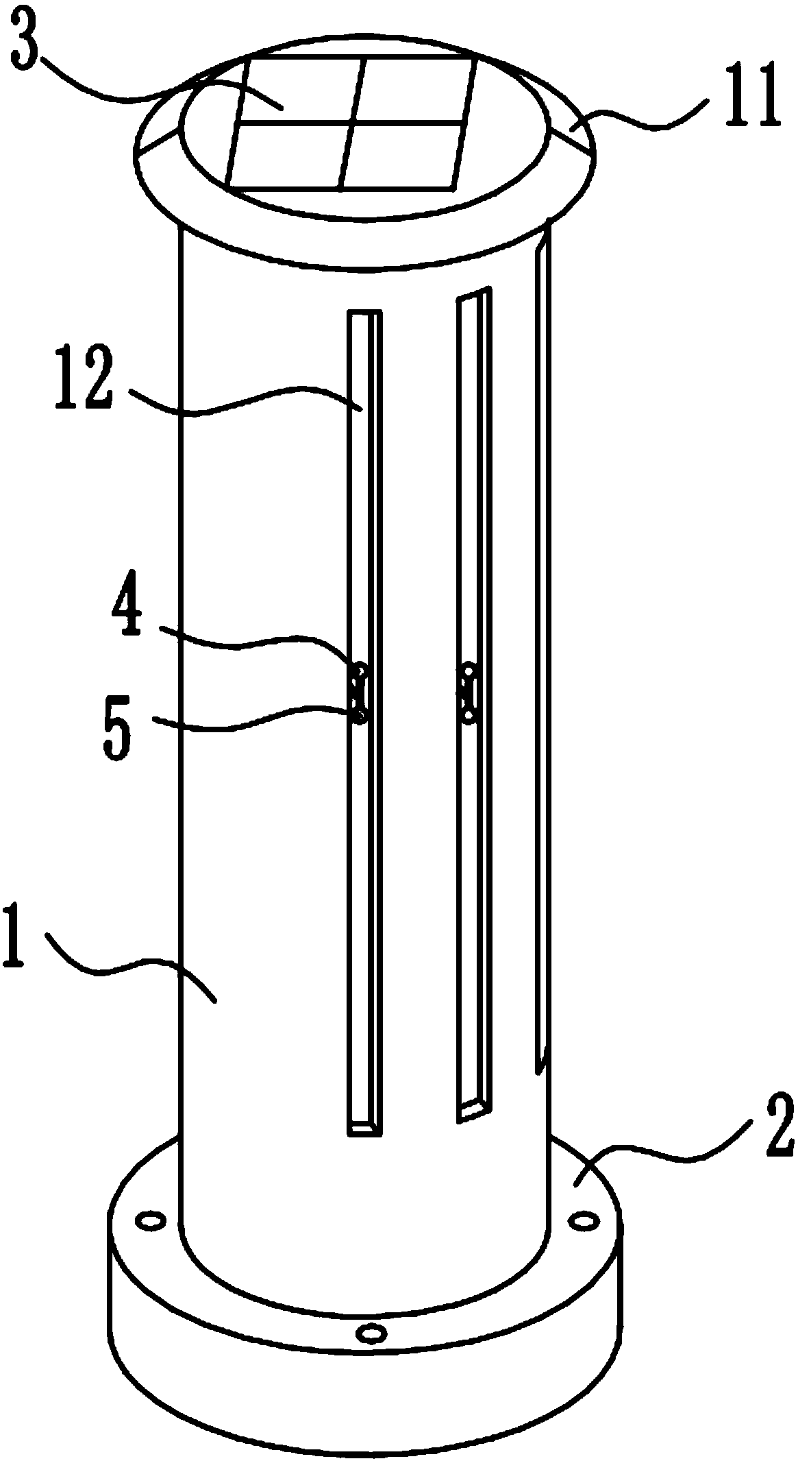
[0034] The reference signs in the accompanying drawings of the specification include: hollow steel column 1 , mounting base 2 , solar panel 3 , infrared emitter 4 , infrared receiver 5 , shielding edge 11 , and bar-shaped hole 12 .

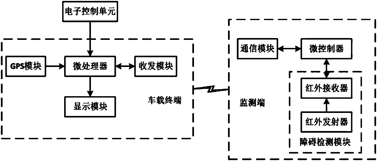
[0035] Obstacle detection systems for traffic intersections, such as figure 1As shown, it includes a vehicle-mounted terminal for installation on a vehicle and a plurality of monitoring terminals for installation on a right-turning curve, and multiple monitoring terminals are respectively installed at a right-turning curve at a traffic intersection, for example, a crossroad at a traffic intersection For example, when the traffic intersection is a T-shaped intersection, three monitoring terminals can be set, and each monitoring terminal has a unique identification number. When setting the number, take true north as the benchmark and move clockwise The direction...


PUM


Abstract

The invention relates to the technical field of barrier monitoring at traffic intersections, in particular to a barrier monitoring system used at a traffic intersection. The barrier monitoring systemcomprises a vehicle-mounted terminal and a plurality of numbered monitoring terminals, wherein the vehicle-mounted terminal is used for being mounted on a vehicle and performing signal transmission and reception; the monitoring terminals are used for being mounted at right-turning bends and conducting barrier detection; the vehicle-mounted terminal comprises a display module, a GPS module, a transceiving module and a microprocessor; and each monitoring terminal comprises a barrier detection module, a communication module and a microcontroller. The barrier monitoring system prompts a driver that a barrier exists in a blind zone of the upcoming right-turning bend in advance on the vehicle-mounted terminal, avoids the driver from having no chance of avoiding the barrier when the driver findsthe barrier after turning, reduces the occurrence of car accidents, only transmits barrier information to the vehicle-mounted terminal by means of the monitoring terminals after the vehicle enters theturning lane, and is more precise and timely.

Description

technical field [0001] The invention relates to the technical field of obstacle monitoring at traffic intersections, in particular to an obstacle monitoring system for traffic intersections. Background technique [0002] With the development of economy and society, the development of traffic roads has been promoted, the number of roads has increased, and the criss-crossing of roads has formed crossroads and T-shaped intersections. When the vehicle drives to such a traffic intersection, the vehicle can go straight, turn left and turn right at the intersection. The vehicle has a wide field of vision when going straight and turning left, and can see obstacles on the road clearly. When the vehicle turns right, due to The green belts or buildings on both sides of the road are blocked, so that the vehicle cannot see the fixed or moving obstacles in the turning direction when turning right, thus forming a blind spot in the turning direction and increasing the probability of car acc...

Claims


Application Information

Patent Timeline
Patent Type & Authority Applications(China)
IPC IPC(8): G08G1/16
CPCG08G1/165G08G1/166
Inventor 刘小瑞周久茗李庆
Owner CHONGQING COLLEGE OF ELECTRONICS ENG
Why Eureka
Try Eureka