
Pre-twisted spacer

A spacer and pre-twisted technology, which is applied in the installation of devices, electrical components, and cables that maintain the distance between parallel conductors, can solve the problems of complicated spacer installation, damage to wires, and affect the performance of wires, so as to improve the electrical isolation effect, The effect of improving force performance and improving safety performance

Inactive Publication Date: 2018-03-27
STATE GRID LIAONING ELECTRIC POWER CO LTD SHENYANG POWER +1
View PDF0 Cites 2 Cited by
  • Summary
  • Abstract
  • Description
  • Claims
  • Application Information

AI Technical Summary

Problems solved by technology

[0002] Spacer rods are required when using overhead conductors. The installation of existing spacer rods is complicated, and stress concentration occurs at the contact points. When subjected to wind loads, suppressing the galloping of the conductors will damage the conductors, and in severe cases, it will cause disconnection accidents, which will cause safety hazards to the power grid. Hidden danger
In addition, bolts or other fastening methods are generally used for the clamps of the existing spacers, so that the fastening operation between the clamps and the wires needs to be realized by using a special spacer wrench, but excessive torque will cause damage to the wires or bolts , while the torque is too small, the grip force between the wire and the anti-vibration hammer will not meet the standard; at the same time, the wire clip will cause local concentrated force on the wire, which will affect the performance of the wire

Method used


Image

  • Pre-twisted spacer
  • Pre-twisted spacer

Examples


Embodiment Construction

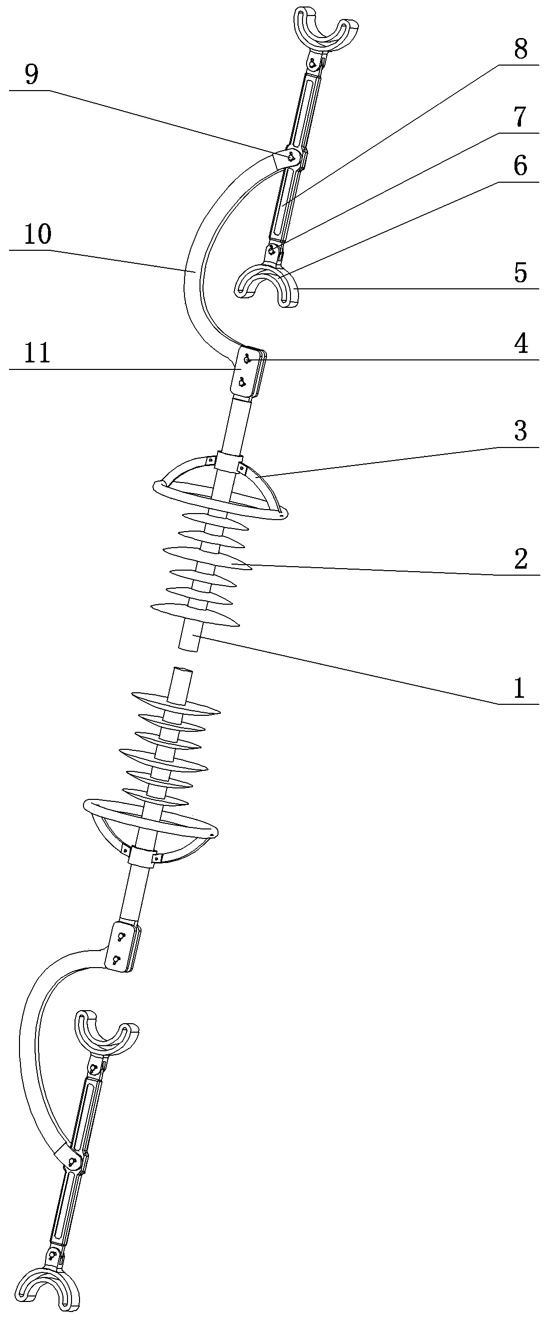
[0021] As shown in the figure, the present invention includes a support rod and a wire clip provided at both ends of the support rod. There are pre-twisted wires in the through hole; the inner end of the clamp is a connecting splint, and the connecting splint and the end of the support rod are correspondingly provided with connecting holes. The end of the support rod is placed in the connecting splint, and a pin passes through the connecting hole. A transverse positioning hole is arranged on the front end rod, and a positioning pin is passed through the positioning hole.

[0022] The middle part of the support rod is connected to one end of the arc-shaped rotary arm through a pin shaft, and the other end of the arc-shaped rotary arm is fixed to the connecting plate at the end of the mandrel. Shed skirts are arranged on both sides of the mandrel, and the shed skirts are close to the end of the mandrel. There is a pressure equalizing ring on the mandrel on the side of the head. ...


PUM


Abstract

A pre-twisted spacer bar belongs to the technical field of spacer devices for overhead wires of power transmission lines, and in particular relates to a pre-twisted spacer bar. The invention provides a pre-twisted spacer bar which can improve the stress performance between the spacer bar and the conductor and is easy to install. The present invention includes a support rod, and its structural points are wire clips arranged at both ends of the support rod. There are pre-twisted wires in the inner thread; the inner end of the clamp is a connecting splint, and the connecting splint and the end of the support rod are provided with a connecting hole correspondingly. There is a horizontal positioning hole on the top, and a positioning pin is inserted in the positioning hole; the middle part of the support rod is connected with one end of the arc-shaped rotary arm through a pin shaft, and the other end of the arc-shaped rotary arm is fixed with the connecting plate at the end of the mandrel, and the mandrel There are umbrella skirt groups on both sides, and a pressure equalizing ring is arranged on the mandrel near the end of the mandrel.

Description

technical field [0001] The invention belongs to the technical field of spacing devices for overhead conductors of power transmission lines, and in particular relates to a pre-twisted spacer bar. Background technique [0002] When using overhead wires, spacers need to be used. The installation of existing spacers is complicated, and there will be stress concentration at the contact points. When subjected to wind loads, suppressing the galloping of the wires will damage the wires, and in severe cases, it will cause disconnection accidents, which will cause safety hazards to the power grid. Hidden danger. In addition, bolts or other fastening methods are generally used for the clamps of the existing spacers, so that the fastening operation between the clamps and the wires needs to be realized by using a special spacer wrench, but excessive torque will cause damage to the wires or bolts , and if the torque is too small, the grip force between the wire and the anti-vibration ham...

Claims


Application Information

Patent Timeline
Patent Type & Authority Applications(China)
IPC IPC(8): H02G7/12H02G7/14
CPCH02G7/125H02G7/14
Inventor 杨长龙谭洪恩陆俊海付沄李悦悦刘文娟张宇夏玉珏张忠瑞付岳峰
Owner STATE GRID LIAONING ELECTRIC POWER CO LTD SHENYANG POWER
Learn More