Motor Stator And Manufacturing Method

A technology of a motor stator and a manufacturing method, which is applied to the field of motor stator and its manufacturing, can solve the problems such as the inability to increase the number of teeth 922 of the stator iron core 92, the difficulty in increasing the torque and rotation speed of the motor, and the waste of material manufacturing costs, thereby achieving improved performance and Quality, reduce the difficulty of winding, reduce the effect of scrap

Active Publication Date: 2018-03-27
SUNON ELECTRONICS (BEIHAI) CO LTD
View PDF5 Cites 1 Cited by
  • Summary
  • Abstract
  • Description
  • Claims
  • Application Information

AI Technical Summary

Problems solved by technology

[0004] However, in the process of punching and forming the plurality of silicon steel sheet rings 91, the metal sheet material band will become waste in the middle and outer periphery of each silicon steel sheet ring 91 due to each stamping; 91’s metal strips have a reasonable spacing, and the proportion of waste is as high as about 70%, which leads to waste of materials and difficulty in reducing manufacturing costs.
[0005] In addition, especially when manufacturing the motor stator 9 for an inner rotor motor, since the stator core 92 has an annular yoke 921 and a plurality of teeth 922 extending from the inner edge of the yoke 921 toward the center, Moreover, a boot 923 is formed at the end of each tooth 922, so the stator core 92 must maintain a sufficient gap between any two adjacent boots 923, so as to ensure that the mold, winding machine and other devices can smoothly carry out the winding operation. However, this winding operation is still not easy to carry out, not only the winding hours are long, but also the situation of accidentally scratching the coil group 94 often occurs in the winding process
Therefore, due to the high difficulty of winding operation, it is almost impossible to increase the number of teeth 922 of the stator core 92 without increasing the size of the stator core 92, and naturally it is difficult to increase the torque and rotational speed of the motor.

Method used


Image

  • Motor Stator And Manufacturing Method
  • Motor Stator And Manufacturing Method
  • Motor Stator And Manufacturing Method

Examples


Embodiment Construction

[0068] In order to make the above-mentioned and other objects, features and advantages of the present invention more comprehensible, the following is based on the preferred embodiments of the present invention and is described in detail as follows in conjunction with the accompanying drawings:

[0069] An embodiment of the manufacturing method of the motor stator of the present invention includes the following steps:

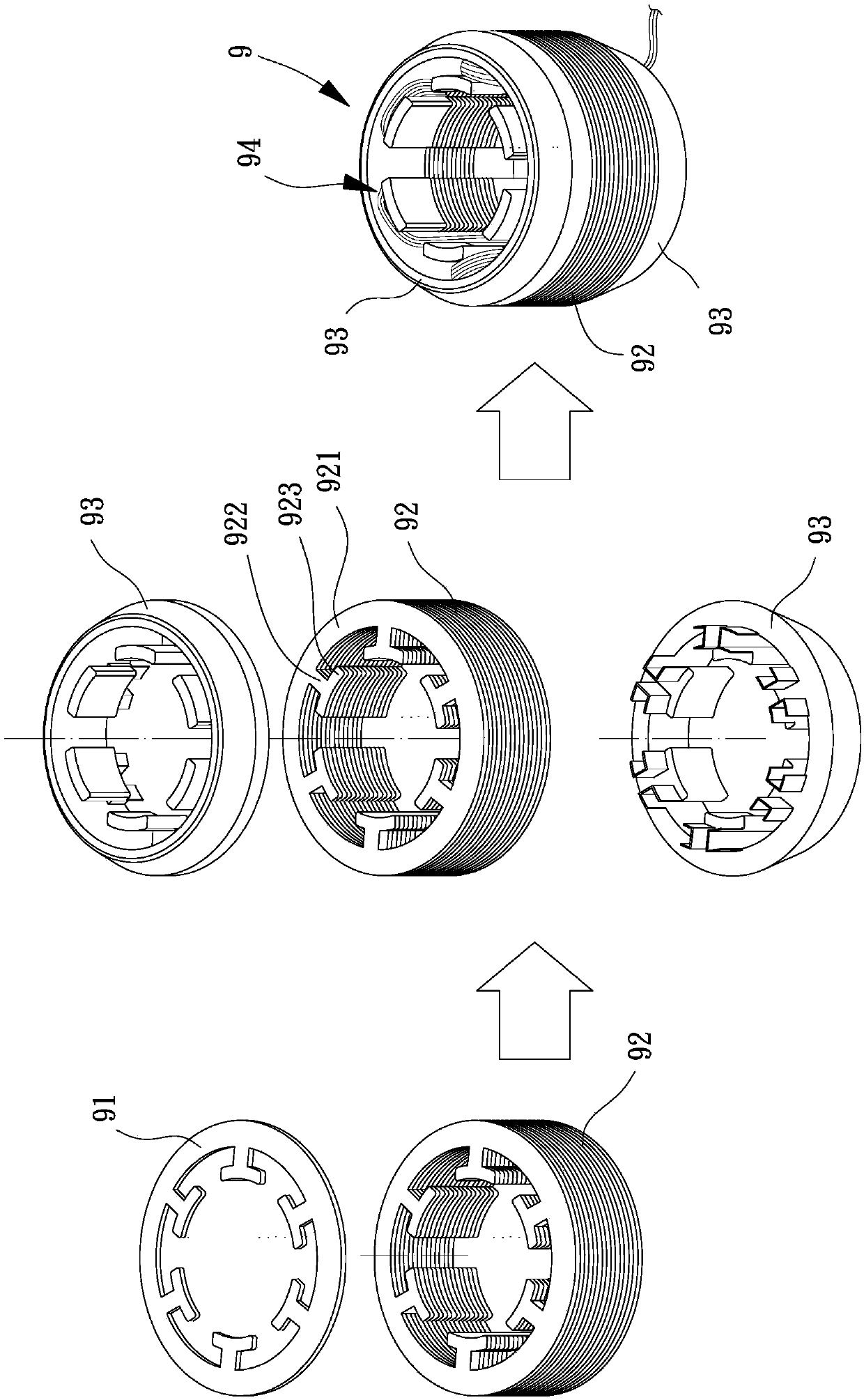
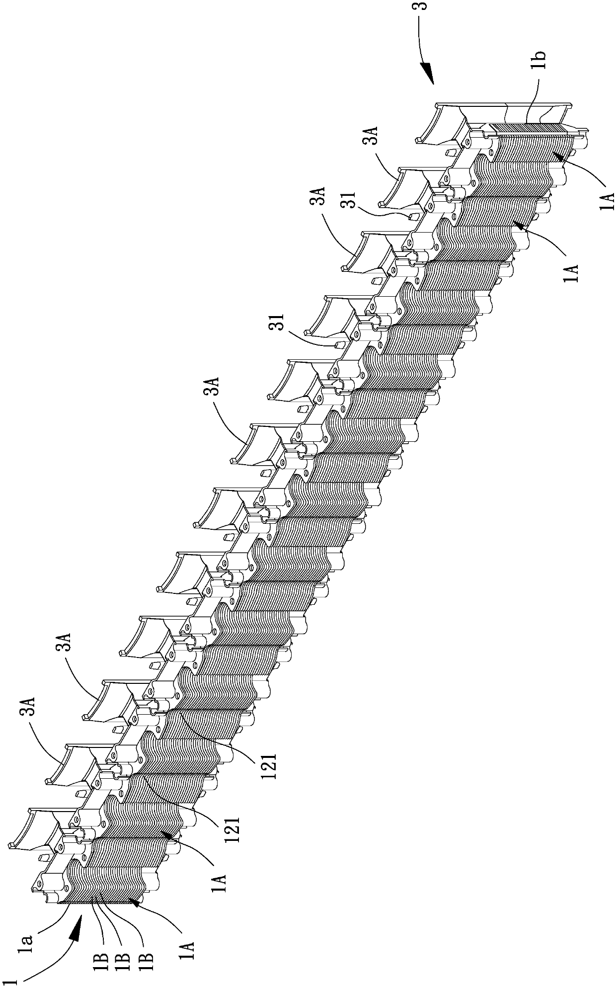
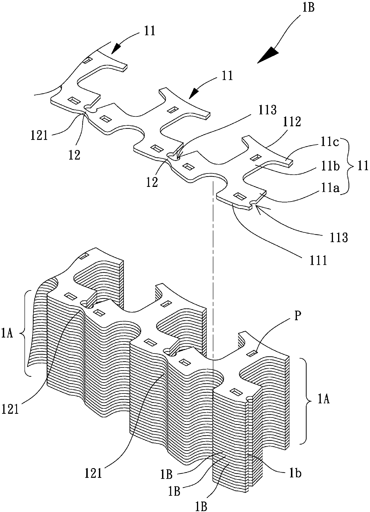
[0070] Please refer to figure 2 , 3 , provide an iron core bar 1, the iron core bar 1 has a plurality of iron core units 1A, and the plurality of iron core units 1A are connected to form a long strip, preferably a straight strip. In this embodiment, the iron core bar 1 can be stacked into a predetermined thickness by a plurality of silicon steel sheets 1B, and each silicon steel sheet 1B has a plurality of silicon steel sheet units 11 horizontally connected in a long series, and each silicon steel sheet unit 11 can be provided with A plurality of riveting poi...


PUM


Abstract

A motor stator and a manufacturing method thereof are provided, in order to solve the problem of high motor stator manufacturing cost. The method for manufacturing a motor stator includes the following steps: providing a core bar having a plurality of connected core units; winding a plurality of coils of a coil group respectively on the plurality of core units; bending the core strip into a core ring; and welding both ends of the core strip with laser, so that the core ring is fixed in a ring shape to form a motor stator.

Description

technical field [0001] The invention relates to the technical field of motors, in particular to a motor stator and a manufacturing method thereof. Background technique [0002] At present, the common motor stators on the market can be roughly divided into the stator of the outer rotor motor and the stator of the inner rotor motor; among them, the manufacturing process and structural composition of the stator of the inner rotor motor and the stator of the outer rotor motor are roughly the same, and the inner rotor motor is as follows Take the stator of the motor as an example to illustrate the current manufacturing method and structure of the motor stator. [0003] Please refer to figure 1 , the existing manufacturing method of the motor stator 9 generally includes the following steps: forming a plurality of annular silicon steel sheet rings 91 in a stamping manner in advance, and stacking and combining the plurality of silicon steel sheet rings 91 into a stator iron sheet w...

Claims


Application Information

Patent Timeline
Patent Type & Authority Applications(China)
IPC IPC(8): H02K1/12H02K15/02
CPCH02K1/12H02K15/02H02K2201/15
Inventor 洪银树尹佐国王启民
Owner SUNON ELECTRONICS (BEIHAI) CO LTD
Why Eureka
Try Eureka