Check patentability & draft patents in minutes with Patsnap Eureka AI!

Punch tool system

A punching and tooling technology, applied in the field of punching tool system, can solve the problem of high cost

Active Publication Date: 2018-03-27
RIDGE TOOL CO
View PDF6 Cites 0 Cited by
  • Summary
  • Abstract
  • Description
  • Claims
  • Application Information

AI Technical Summary

Problems solved by technology

Battery powered tools also cost more than hand tools

Method used


Image

  • Punch tool system
  • Punch tool system
  • Punch tool system

Examples


Embodiment Construction

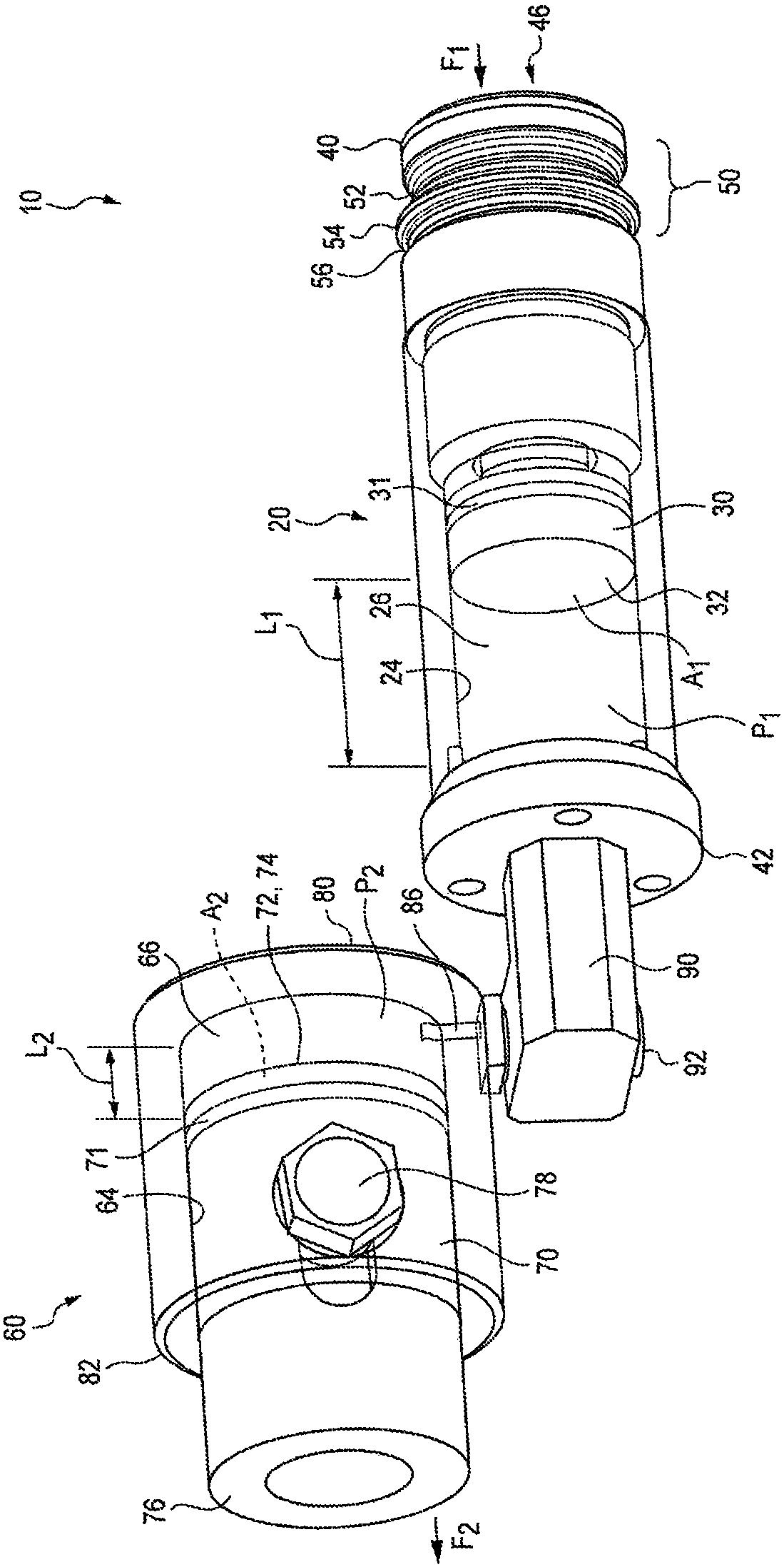
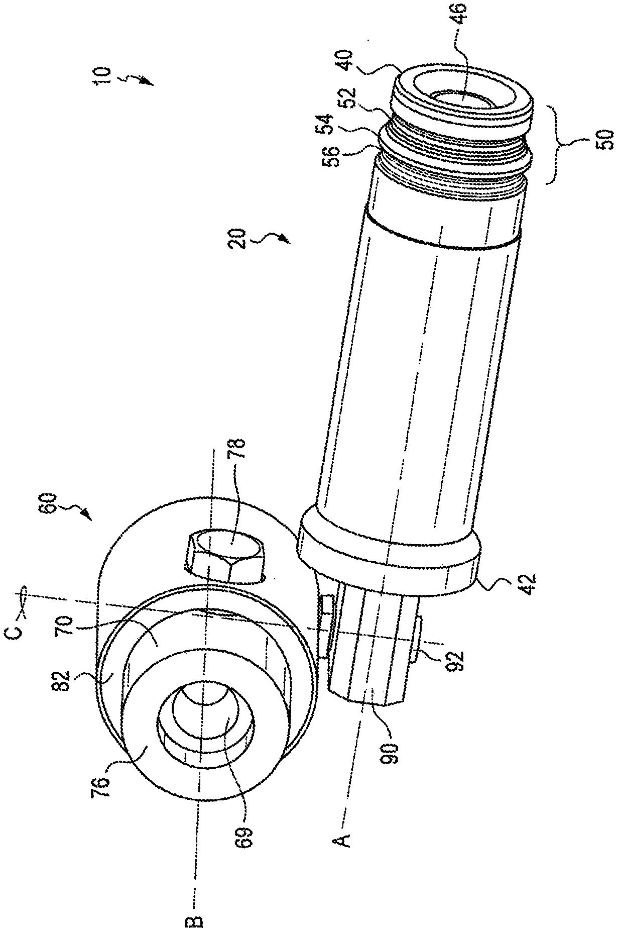
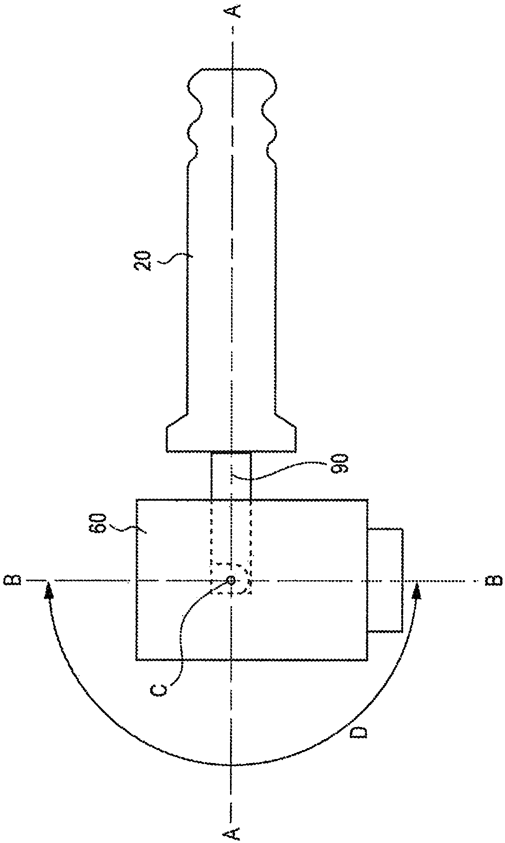
[0023] The subject matter relates to non-powered punching tools for forming holes or bores in workpieces such as sheet metal. The piercing tool includes a master cylinder having a linearly moveable plunger disposed within a chamber defined within the master cylinder, and a slave cylinder having a linearly moveable plunger disposed within a chamber defined within the slave cylinder . The slave cylinder is movable relative to the master cylinder. The chamber of the master cylinder is in hydraulic communication with the chamber of the slave cylinder such that linear displacement of either plunger results in a corresponding linear displacement of the other plunger. The master cylinder may be releasably engageable with a punch tool or other device that provides powered extension of a plunger or other member. The plunger or member of the punching tool displaces the plunger of the master cylinder by extending, thereby causing the displacement of the plunger of the slave cylinder. ...


PUM


Abstract

The present invention describes a punch tool for forming holes or apertures in workpieces. The tool includes a primary cylinder containing a movable ram and a secondary cylinder containing another movable ram. The primary and secondary cylinders are in hydraulic communication with each other. The primary cylinder is releasably engageable with a powered press tool and various dies or punches can beattached at the secondary cylinder. Also described are systems of powered tools and the punch tools, and methods of forming holes in workpieces using the punch tools.

Description

technical field [0001] The present invention relates to a tool for forming holes in various workpieces such as metal plates, and more particularly to a punching tool that can be engaged with a hydraulic punching tool. Background technique [0002] To install electrical components, electrical contractors use tools that create large round and square holes in electrical enclosures. These enclosures are usually made of mild steel or stainless steel sheet metal. The tools used for this purpose are well known in the industry and generally require the drilling of a pilot hole and a draw bolt inserted into the hole to apply the load to the die, usually called a jack. Draw bolts and jacks are often standardized and interchangeable with various tools to transfer the required punching force. [0003] Holes can be formed in the sheet using various types and kinds of tools. Relatively simple tools can be used that use a draw bolt or similar member to apply the load and require a ratch...

Claims


Application Information

Patent Timeline
IPC IPC(8): B25F3/00B26F1/34B26F1/40B26D5/12B26D7/26B26D5/04B21D28/34B30B1/32F16B21/16
CPCB21D28/26B21D28/002B21D28/34B21D28/343B25F5/005B26D5/12
Inventor R·M·昆德拉齐M·伯特伦R·M·鲍劳奇考伊
Owner RIDGE TOOL CO
Features
  • R&D
  • Intellectual Property
  • Life Sciences
  • Materials
  • Tech Scout
  • Unparalleled Data Quality
  • Higher Quality Content
  • 60% Fewer Hallucinations
Learn More