High-efficiency mixing device for raw material for producing brake clutch disc

A technology of mixing device and clutch plate, which is applied in the direction of mixer, fluid mixer, transportation and packaging, etc., can solve the problems of slow mixing speed, uneven mixing, high labor intensity, etc.

Inactive Publication Date: 2018-03-30
闫梦蝶
View PDF2 Cites 23 Cited by
  • Summary
  • Abstract
  • Description
  • Claims
  • Application Information

AI Technical Summary

Problems solved by technology

[0005] In order to overcome the shortcomings of uneven mixing, high labor intensity and slow mixing speed in the existing mixing device, the technical problem to be solved by the invention is to provide a brake clutch plate production line with uniform mixing, low labor intensity and fast mixing speed. Efficient mixing device for raw materials

Method used


Image

  • High-efficiency mixing device for raw material for producing brake clutch disc
  • High-efficiency mixing device for raw material for producing brake clutch disc
  • High-efficiency mixing device for raw material for producing brake clutch disc

Examples


Embodiment 1

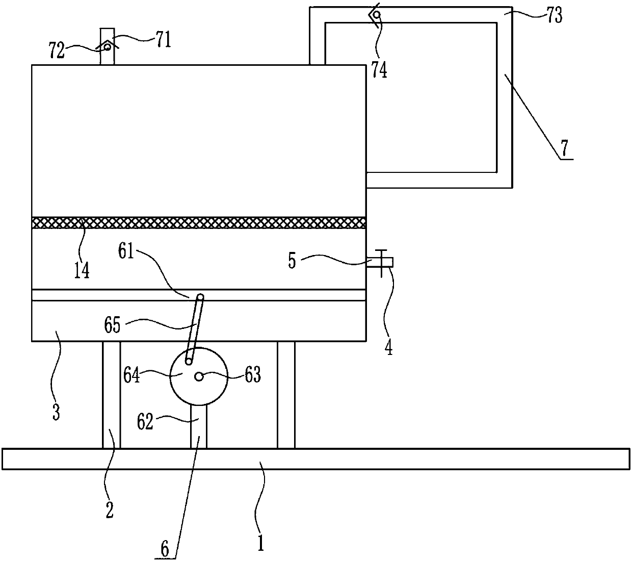
[0035] A high-efficiency mixing device for raw materials used in the production of brake clutch plates, such as Figure 1-5As shown, it includes a bottom plate 1, a pole 2, a first box body 3, a first discharge pipe 4, a valve 5, a mesh plate 14, a driving device 6 and a mixing structure 7, and the left and right sides of the bottom left side of the bottom plate 1 are both A support rod 2 is installed by means of bolt connection, the top of the support rod 2 is provided with a first box body 3, and the lower right side of the first box body 3 is installed with a first discharge pipe 4, and a valve is provided on the first discharge pipe 4 5. A mesh plate 14 is installed in the middle of the first box 3, and a driving device 6 is installed on the top of the bottom plate 1 between the two poles 2. The driving part of the driving device 6 is located at the bottom of the first box 3. The first box 3 The upper part and the right side are equipped with a mixing structure 7.

Embodiment 2

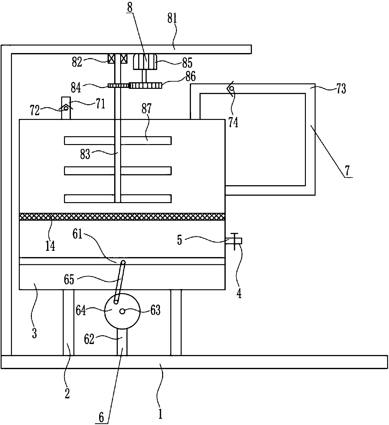
[0037] A high-efficiency mixing device for raw materials used in the production of brake clutch plates, such as Figure 1-5 As shown, it includes a bottom plate 1, a pole 2, a first box body 3, a first discharge pipe 4, a valve 5, a mesh plate 14, a driving device 6 and a mixing structure 7, and the left and right sides of the bottom left side of the bottom plate 1 are both A support rod 2 is installed by means of bolt connection, the top of the support rod 2 is provided with a first box body 3, and the lower right side of the first box body 3 is installed with a first discharge pipe 4, and a valve is provided on the first discharge pipe 4 5. A mesh plate 14 is installed in the middle of the first box 3, and a driving device 6 is installed on the top of the bottom plate 1 between the two poles 2. The driving part of the driving device 6 is located at the bottom of the first box 3. The first box 3 The upper part and the right side are equipped with a mixing structure 7.

[003...

Embodiment 3

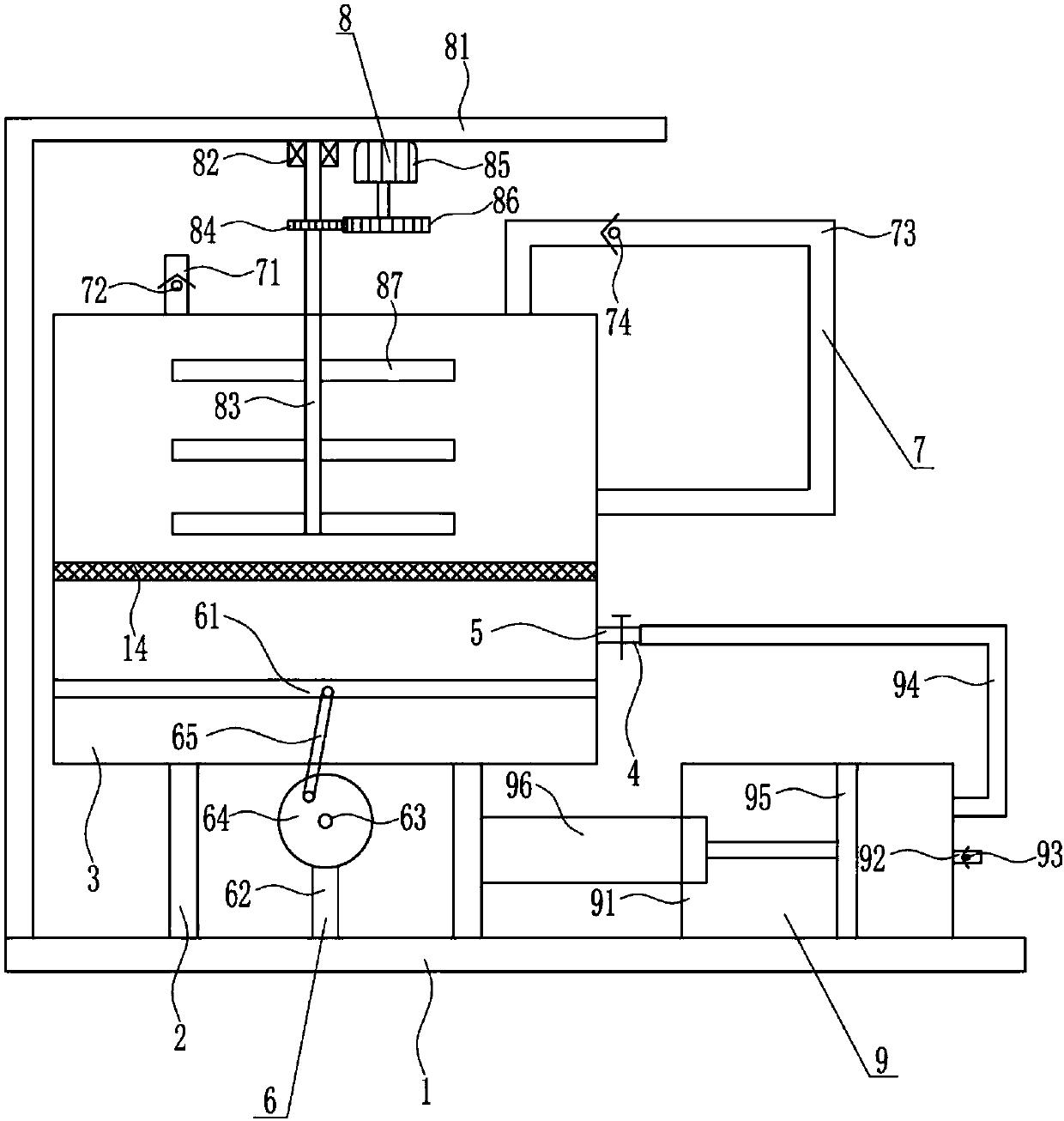
[0040] A high-efficiency mixing device for raw materials used in the production of brake clutch plates, such as Figure 1-5 As shown, it includes a bottom plate 1, a pole 2, a first box body 3, a first discharge pipe 4, a valve 5, a mesh plate 14, a driving device 6 and a mixing structure 7, and the left and right sides of the bottom left side of the bottom plate 1 are both A support rod 2 is installed by means of bolt connection, the top of the support rod 2 is provided with a first box body 3, and the lower right side of the first box body 3 is installed with a first discharge pipe 4, and a valve is provided on the first discharge pipe 4 5. A mesh plate 14 is installed in the middle of the first box 3, and a driving device 6 is installed on the top of the bottom plate 1 between the two poles 2. The driving part of the driving device 6 is located at the bottom of the first box 3. The first box 3 The upper part and the right side are equipped with a mixing structure 7.

[004...


PUM


Abstract

The invention relates to a mixing device for a raw material, and particularly relates to a high-efficiency mixing device for a raw material for producing a brake clutch disc. The invention aims at solving the technical problem of providing a high-efficiency mixing device for the raw material for producing the brake clutch disc, which is uniform in mixing, low in labor intensity and quick in mixingspeed. In order to solve the technical problem, the invention provides such a high-efficiency mixing device for the raw material for producing the brake clutch disc. The high-efficiency mixing devicecomprises a bottom plate, supporting rods, a first box body, a first discharge pipe, a valve and the like, wherein the left and right sides of the bottom left side of the bottom plate are both provided with the supporting rods through a bolt connection way; the first box body is arranged at the tops of the supporting rods; the lower part of the right side of the first box body is provided with the first discharge pipe; the first discharge pipe is provided with the valve; the middle part in the first box body is provided with a reticular plate. The high-efficiency mixing device is used for realizing the effect of the high-efficiency mixing device for the raw material for producing the brake clutch disc, which is uniform in mixing, low in labor intensity and quick in mixing speed.

Description

technical field [0001] The invention relates to a raw material mixing device, in particular to a high-efficiency mixing device for raw materials used in the production of brake clutch plates. Background technique [0002] Brake pads are also called brake pads. In the braking system of a car, the brake pads are the most critical safety parts. The brake pads play a decisive role in the quality of all braking effects, so good brake pads are the protectors of people and cars. [0003] The raw materials need to be mixed during the production process of brake clutch pads. The existing mixing devices have the disadvantages of uneven mixing, high labor intensity, and slow mixing speed. High-efficiency mixing device for raw materials for clutch disc production. Contents of the invention [0004] (1) Technical problems to be solved [0005] In order to overcome the disadvantages of uneven mixing, high labor intensity and slow mixing speed in the existing mixing device, the techni...

Claims


Application Information

Patent Timeline
Patent Type & Authority Applications(China)
IPC IPC(8): B01F13/10B01F5/10
CPCB01F25/50B01F33/82
Inventor 闫梦蝶韩雅静王静田
Owner 闫梦蝶
Why Eureka
Try Eureka