Cast-in-place prefabricated composite structure pile suitable for karst zone and construction method of cast-in-place prefabricated composite structure pile

A technology of combined structure and construction method, applied in foundation structure engineering, sheet pile walls, buildings, etc., can solve problems such as high cost, inability to take out, construction personnel casualties, etc., and achieve obvious economic benefits, fast construction speed, and convenient construction Effect

Active Publication Date: 2018-03-30
HUBEI UNIV OF TECH
View PDF4 Cites 6 Cited by
  • Summary
  • Abstract
  • Description
  • Claims
  • Application Information

AI Technical Summary

Problems solved by technology

[0002] When constructing pile foundations in karst-developed areas, when the borehole encounters a large-scale karst cave, the retaining wall mud in the borehole often loses rapidly and causes the hole to collapse, resulting in property loss and construction personnel casualties. Delay
In order to prevent ...

Method used


Image

  • Cast-in-place prefabricated composite structure pile suitable for karst zone and construction method of cast-in-place prefabricated composite structure pile
  • Cast-in-place prefabricated composite structure pile suitable for karst zone and construction method of cast-in-place prefabricated composite structure pile
  • Cast-in-place prefabricated composite structure pile suitable for karst zone and construction method of cast-in-place prefabricated composite structure pile

Examples


Embodiment Construction

[0029] The present invention is further described below in conjunction with the accompanying drawings. The following is only an example of the technical solutions of the present invention, and does not represent the scope of all technical solutions of the present invention. In addition, the terms used in the embodiments have clear definitions, which are subject to their definitions, and there is no clear definition. The general explanations in the industry shall prevail, and the structure or steps not mentioned in the following embodiments are existing mature technologies.

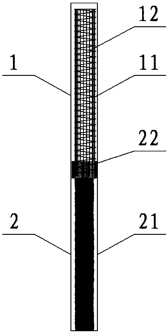
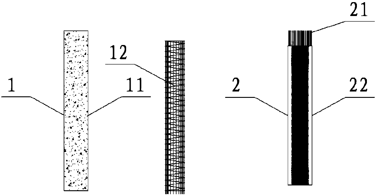
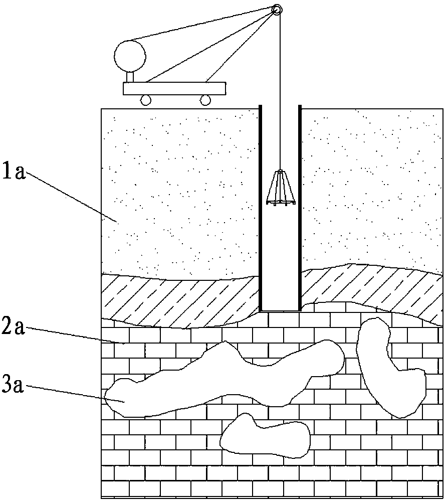
[0030] Such as figure 1 and figure 2 As shown, a cast-in-place prefabricated composite structural pile suitable for karst areas includes an upper section pile 1 and a lower section pile 2, the upper section pile 1 is a cast-in-situ reinforced concrete pouring pile 11, and the lower section pile 2 is a prefabricated concrete pipe pile 22, The lower pile 2 passes through the karst cave area 2a in the rock ...


PUM


Abstract

The invention discloses a cast-in-place prefabricated composite structure pile suitable for a karst zone and a construction method of the cast-in-place prefabricated composite structure pile. The cast-in-place prefabricated composite structure pile comprises an upper pile section and a lower pile section, the upper pile section is a cast-in-place reinforced concrete grouting pile, the lower pile section is a prefabricated concrete tubular pile, the lower pile section penetrates a karst cave zone in a rock stratum, the upper pile section penetrates a non-karst-cave zone and is supported to theupper end of the lower pile section, and a pile foundation is jointly formed by combining the upper pile section and the lower pile section; in the construction process, an upper-layer non-karst-cavezone pile hole is constructed in a conventional method firstly, then a manual hole digging method or a rotary drilling rig is adopted for constructing a lower-layer karst cave zone pile hole, then theconcrete tubular pile is hoisted into the karst cave zone pile hole, a sealing ring is arranged between the top of the concrete tubular pile and the non-karst-cave zone pile hole, then a reinforcement cage of the reinforced concrete grouting pile is hoisted into the non-karst-cave zone pile hole, and cast-in-place grouting is carried out to obtain the overall pile foundation integrating the concrete tubular pile with the reinforced concrete grouting pile. According to the cast-in-place prefabricated composite structure pile and the construction method, the upper pile section and the lower pile section are combined to form an overall pile body to achieve joint stress, construction is convenient and quick, and the construction cost is low.

Description

technical field [0001] The invention belongs to the technical field of piles in civil engineering, and in particular relates to a cast-in-place prefabricated composite structure pile suitable for karst areas and a construction method thereof. Background technique [0002] When constructing pile foundations in karst-developed areas, when the borehole encounters a large-scale karst cave, the retaining wall mud in the borehole often loses rapidly and causes the hole to collapse, resulting in property loss and construction personnel casualties. Delay in construction period. In order to prevent such accidents, the usual practice is to drill steel pipe casings into the rock surface as a maintenance structure. This kind of steel casing is only a construction measure, and the force of the permanent structure does not take it into account, and it cannot be taken out after the pile is formed. , the cost is higher. Contents of the invention [0003] The purpose of the present inven...

Claims


Application Information

Patent Timeline
IPC IPC(8): E02D5/50E02D5/52
Inventor 刘永莉肖衡林马强周文佐李丽华何俊黄思璐巴军涛柏华军
Owner HUBEI UNIV OF TECH
Why Eureka
Try Eureka