Light emitting assembly, packaging process and optical module

A technology of optical emission components and packaging technology, which is applied in the field of optical communication, and can solve problems such as difficult implementation and difficult fiber optic technology

Active Publication Date: 2018-03-30
SHENZHEN GIGALIGHT TECH
View PDF6 Cites 24 Cited by
  • Summary
  • Abstract
  • Description
  • Claims
  • Application Information

AI Technical Summary

Problems solved by technology

[0006] The embodiment of the present application provides an optical emission component, a packaging process and an optical module to solve the problems in the prior art that the disk fiber process is difficult and difficult to implement

Method used


Image

  • Light emitting assembly, packaging process and optical module
  • Light emitting assembly, packaging process and optical module
  • Light emitting assembly, packaging process and optical module

Examples


Embodiment Construction

[0035] In order to solve the problem that the disk fiber process in the prior art is difficult and not easy to implement, the embodiments of the present application provide a light emitting component, a packaging process and an optical module.

[0036] The preferred embodiments of the present application will be described below in conjunction with the accompanying drawings. It should be understood that the preferred embodiments described here are only used to illustrate and explain the present application, and are not intended to limit the present application. And in the case of no conflict, the embodiments in the present application and the features in the embodiments can be combined with each other.

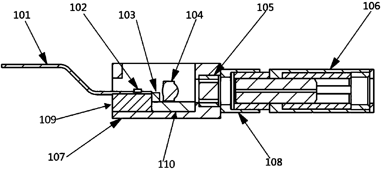
[0037] Such as figure 1 As shown, it is a schematic structural diagram of some components of the TOSA provided by the embodiment of the present application, including: a flexible circuit board 101, a laser chip 103, a backlight detector 102, a coupling lens 104, an isolator 105...


PUM


Abstract

An embodiment of the invention provides a light emitting assembly, a packaging process and an optical module, wherein the light emitting assembly, the packaging process and the optical module are usedfor settling problems of high difficulty and no easy realization of a fiber coiling process in prior art. The light emitting assembly comprises the components of a flexible circuit board which is used for supplying electric energy to a laser chip and a backlight detector and transmitting an electric signal; the laser chip which is used for receiving the electric signal and converting the electricsignal to an optical signal; a coupling lens which is used for focusing the optical signal that is emitted from the laser chip, wherein the optical signal is transmitted to a single-mode fiber insertion core of a first adapter; and a substrate which is used for supplying an optical path coupling medium for the laser chip and the coupling lens. Because the new light emitting assembly which can beconnected with a multiplexing assembly in a non-welding manner is presented, the fiber coiling process is prevented, and the problems of high difficulty and no easy realization of the fiber coiling process in the existing light emitting assembly are prevented.

Description

technical field [0001] The present application relates to the technical field of optical communication, in particular to an optical emitting component, a packaging process and an optical module. Background technique [0002] As people's requirements for data transmission rates are getting higher and higher, the 100G optical module market is also expanding rapidly. 100GCWDM4QSFP28 is a standard published by the CWDM4MSA organization in 2014. It is a 100G transmission mode based on single-mode coarse wavelength division multiplexing (CWDM, Coarse Wavelength Division Multiplexer) technology. The 100GCWDM4QSFP28 optical module conforming to this standard adopts a duplex LC interface. The four central wavelengths of 1271nm, 1291nm, 1311nm and 1331nm are used for optical signal transmission, and each band transmits 25G. Through CWDM technology, the 100G CWDM4QSFP28 optical module can multiplex the above four central wavelengths onto a single-mode fiber for transmission. [0003]...

Claims


Application Information

Patent Timeline
Patent Type & Authority Applications(China)
IPC IPC(8): G02B6/42
CPCG02B6/4204G02B6/4281G02B6/4296
Inventor 黄钊潘儒胜肖潇李振东
Owner SHENZHEN GIGALIGHT TECH
Why Eureka
Try Eureka