A battery module glue filling tank device

A battery module and glue filling technology, which is applied to primary batteries, primary battery manufacturing equipment, battery assembly machines, etc., can solve the problems of small battery cell assembly gap, low glue filling efficiency, poor contact, etc., and achieve low investment cost , High glue filling efficiency, good conductivity effect

Active Publication Date: 2020-01-10
烟台金潮宇科蓄电池有限公司
View PDF7 Cites 0 Cited by
  • Summary
  • Abstract
  • Description
  • Claims
  • Application Information

AI Technical Summary

Problems solved by technology

[0005] Among them, patent 1, "a glue filling process for a safe power battery module", pours glue from the top of the battery cell into the gap between the single cells of the battery pack. During the glue filling process, it is easy to overflow the glue and bond the battery The positive and negative shrapnel of the cell leads to poor contact, and the assembly gap of the cell is small, the glue filling efficiency is low, and it is time-consuming and laborious
[0006] Patent 2, "a battery module glue filling device" solves the problem of patent 1 to a certain extent, which can avoid glue overflow, and then prevent glue from adhering to the positive and negative electrodes of the battery cell, and ensure that the battery module has good conductivity , the efficiency is also greatly improved, but its disadvantage is that the battery pack cannot be fixed with the upper and lower brackets, and a glue filling device needs to be invested, which increases the equipment cost

Method used


Image

  • A battery module glue filling tank device
  • A battery module glue filling tank device
  • A battery module glue filling tank device

Examples


Embodiment 1

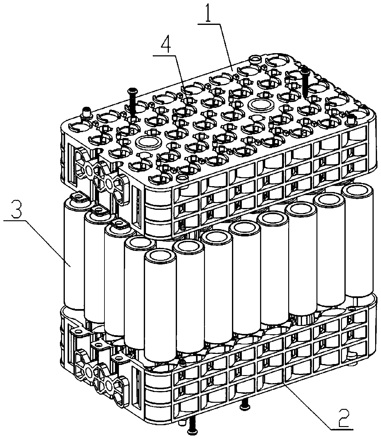
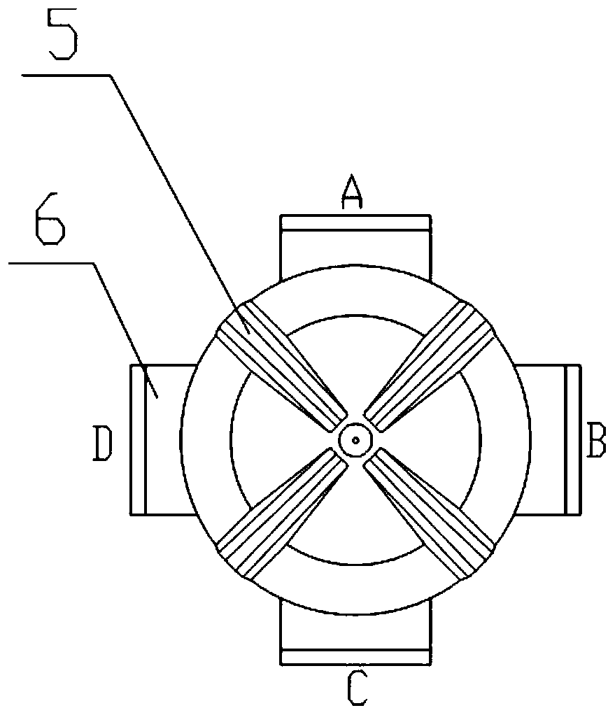
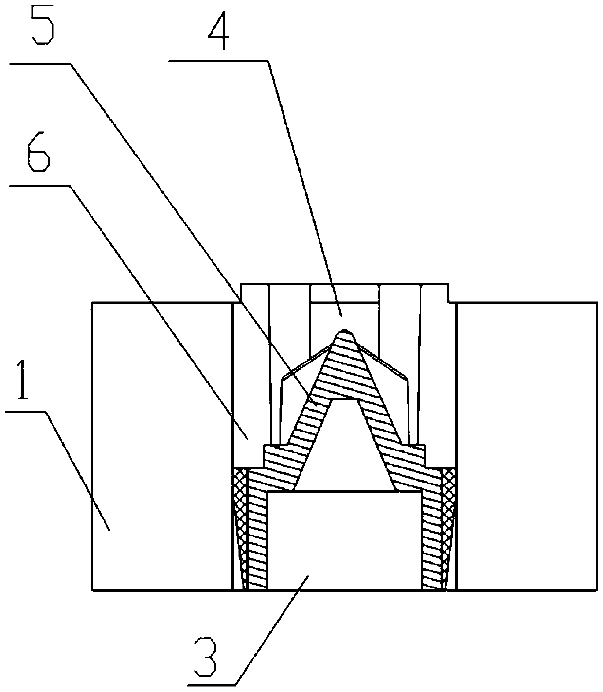
[0026] like figure 1 figure 2 image 3 The battery module glue filling tank device shown includes an upper bracket 1 and a lower bracket 2. The battery cell 3 of the battery module is installed in the middle of the two brackets. The upper bracket 1 and the lower bracket 2 are provided with glue filling The hole 4 and the glue filling hole 4 are cylindrical counterbore structures; the middle of the glue filling hole 4 is provided with a cross-shaped baffle 5, which divides the glue filling hole 4 into several glue filling areas, and there are guides connected to the glue filling areas. The glue groove 6 and the glue guide groove 6 have a rectangular cross section extending into the inside of the two brackets and communicate with the installation cavity of the battery cell 3; a clamping area is formed between the bottoms of each of the glue guide grooves 6, and the clamping area Clamp the outer edge of the battery cell 3, and chamfer the bottom of the glue guide groove 6 to f...

Embodiment 2

[0029] like Figure 4 In the battery module glue filling groove device shown, there are three glue guide grooves, and the order of glue filling is clockwise.

Embodiment 3

[0031] like Figure 5 In the battery module glue filling tank device shown, there are four glue guide grooves, there is no baffle to separate the glue filling area, and the order of glue filling is clockwise.


PUM


Abstract

The invention provides a battery module glue filling tank device. It includes an upper bracket and a lower bracket, and the battery cell of the battery module is installed between the two brackets. Both the upper bracket and the lower bracket are provided with glue filling holes, and the glue filling holes are cylindrical sink hole structures; There is a cross-shaped baffle in the middle of the glue hole, which divides the glue filling hole into several glue filling areas. Next to the glue filling area, there is a glue guide groove. The cross section of the glue guide groove is a rectangular groove extending into the two brackets. The installation cavities of the cores communicate with each other; a clamping area is formed between the bottoms of the respective glue guide grooves, and the clamping area clamps the outer edge of the battery core. The invention has simple structure and convenient operation, prevents glue overflowing during the glue pouring process, ensures good electrical conductivity of the battery module, and has low investment cost and high glue pouring efficiency.

Description

technical field [0001] The invention relates to the technical field of battery module installation, in particular to a battery module glue tank device used for glue-filling and bonding the battery cell and the cell cavity of the module bracket after the battery cell is installed. Background technique [0002] With the maturity of battery module technology, various module manufacturers have gradually realized the advantages of the battery module glue filling process, such as preventing battery shaking and shock absorption, which can alleviate battery fire and explosion. Glue scheme, details are as follows: [0003] Patent CN201610938155.9 "A glue filling process for safe power battery modules" proposes that the upper and lower brackets connected in a detachable manner are used to assemble the battery module first, and then use the glue filling machine to pour glue from the top of the battery cell into the battery pack The gaps between the single cells until all the gaps betw...

Claims


Application Information

Patent Timeline
Patent Type & Authority Patents(China)
IPC IPC(8): H01M6/00H01M10/04
CPCH01M6/005H01M10/0404H01M10/0422Y02E60/10Y02P70/50
Inventor 胡鹏徐长成童少波
Owner 烟台金潮宇科蓄电池有限公司
Why Eureka
Try Eureka