Electric connecting equipment and method for manufacturing same

An electrical connection and equipment technology, applied in the field of electrical connection equipment, can solve problems such as difficult costs, and achieve the effects of high mechanical strength, low transition resistance, and high current carrying capacity

Inactive Publication Date: 2018-03-30
LISA DRAXLMAIER GMBH
View PDF18 Cites 10 Cited by
  • Summary
  • Abstract
  • Description
  • Claims
  • Application Information

AI Technical Summary

Problems solved by technology

[0007] The electrical contacting of the cables on such flat busbars is of course sometimes relatively difficult and cost-intensive

Method used


Image

  • Electric connecting equipment and method for manufacturing same
  • Electric connecting equipment and method for manufacturing same
  • Electric connecting equipment and method for manufacturing same

Examples


Embodiment Construction

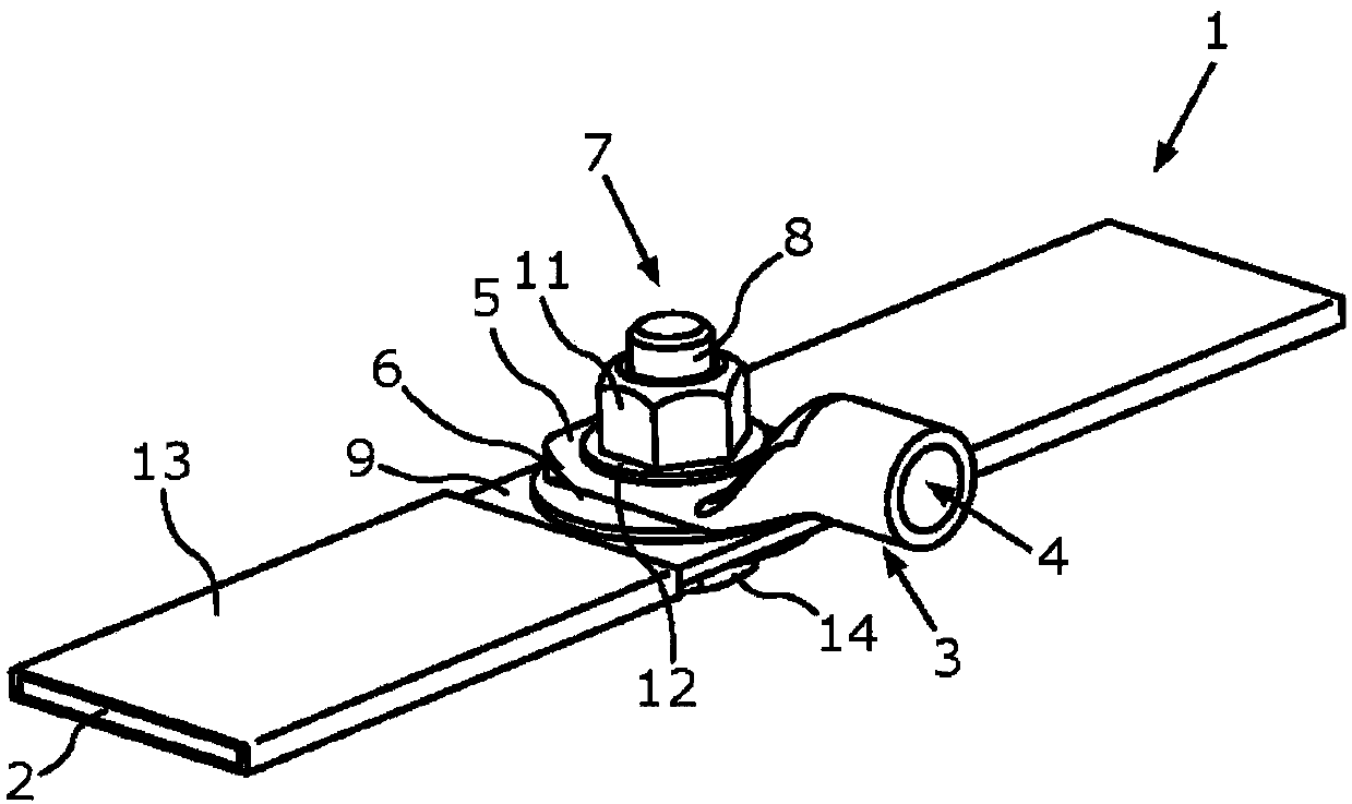
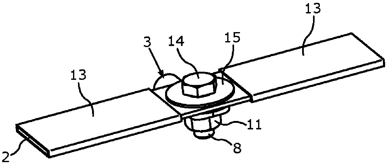
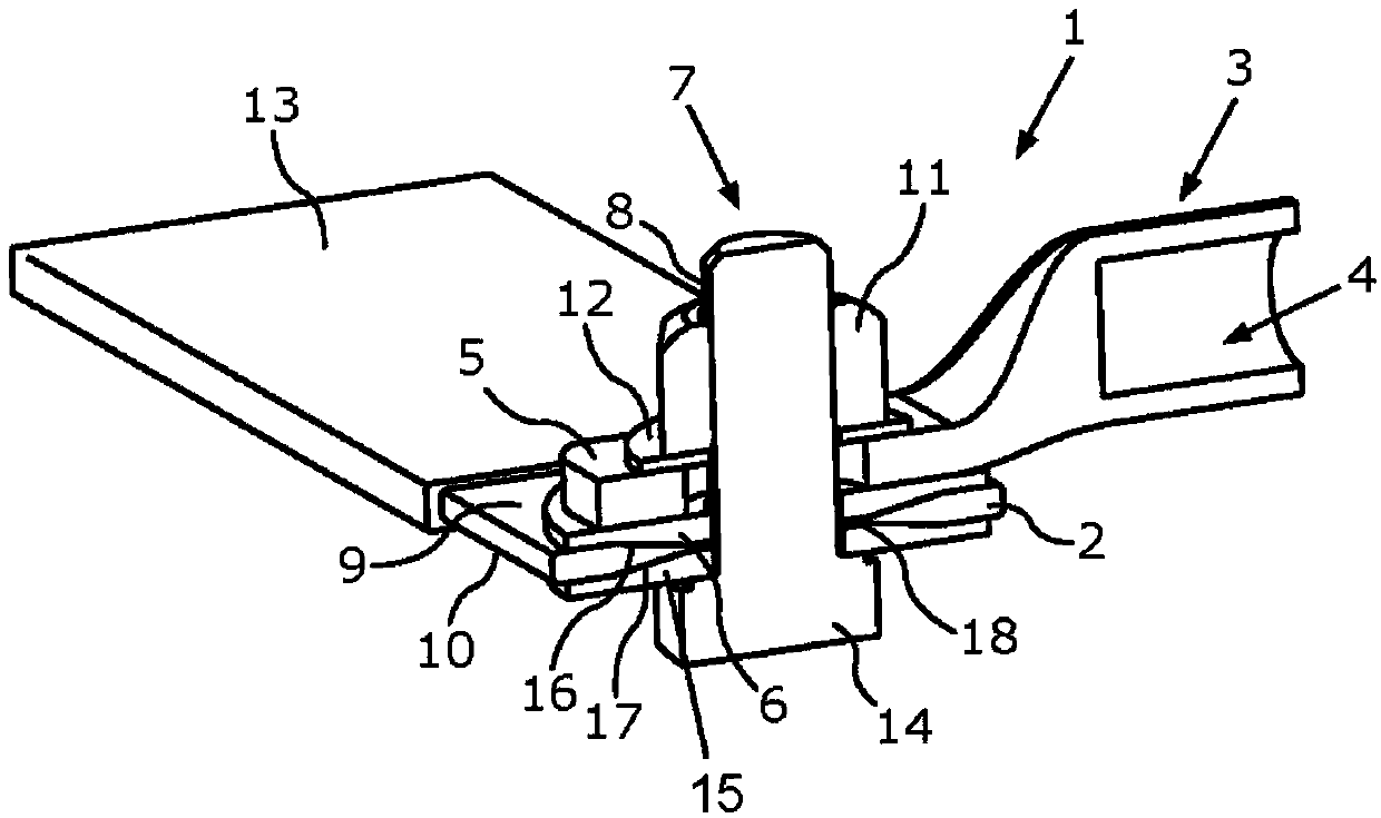
[0049] exist figure 1 The first embodiment of the electrical connection device 1 is shown obliquely from above in a perspective view. The electrical connection device 1 comprises a flat bus bar 2 made of aluminum, on which a cable shoe 3 is fastened. The cable shoe 3 serves as a cable receiving element for electrically conductively connecting a cable (not shown here) to the flat busbar 2 . For receiving cables, the cable boot 3 comprises a cylindrical receiving area 4 . For example, cables formed as flexible round conductors or stranded conductors can be received via the receiving area 4 . The cable shoe 3 is electrically conductively connected with the flattened contact area 5 by means of the contact element 6 to the flat bus bar 2 . The flat bus bar 2 can be specially built in the vehicle for power supply or grounding.

[0050] The flat bus bar 2 includes through-openings, not visible here, through which the screws 7 are guided with their shafts. The through-opening ext...


PUM


Abstract

The invention relates to electric connecting equipment (1) which comprises the components of a flat busbar (2) with a through opening, wherein the through opening extends through the first surface side (9) and the second surface side (10) of the flat busbar; a cable receiving component (3) which is used for conductively connecting the cable with the flat busbar; a screw (7), wherein the rod (8) ofthe screw is guided from the second surface side through the through opening of the flat busbar and through the contact area (5) of the cable receiving component; a nut (11) which is screwed on the rod of the screw, wherein the contact area of the cable receiving component is at least indirectly clamped between the nut and the first surface side through the nut; and contact elements (6,14,19,24)which is connected with the flat busbar material in a combined manner in annular combining areas (16,21,25) which surround the through opening, and furthermore the contact area of the cable receivingcomponent is directly placed on the contact component. The invention further relates to a method for manufacturing the electric connecting equipment.

Description

technical field [0001] The invention relates to an electrical connection device and a method for manufacturing an electrical connection device. Background technique [0002] Due to the increased use of different material combinations in the vehicle body up to the complete manufacture of the vehicle body from carbon fiber reinforced plastics, for example in the case of so-called monocoque structures, the electrical grounding through the body is significantly affected, or in extreme cases Makes electrical grounding completely inoperable. [0003] Ground currents, for example conducted via so-called ground combs, always follow the path of least resistance. Due to the use of different body materials and connection techniques, such as gluing, riveting, welding, etc., the ground current can flow from the consumer to the battery of the vehicle indefinitely or without direction. It can thus happen that the ground current and the spatially separated supply current form an electroma...

Claims


Application Information

Patent Timeline
Patent Type & Authority Applications(China)
IPC IPC(8): H01R4/34H01R4/64H01R43/26
CPCH01R4/34H01R4/64H01R43/26H01R2201/26H01R4/62
Inventor 沃尔夫冈·维默尔托马斯·赫青克劳斯·史派西约翰纳斯·玻勒约瑟夫·山德尔
Owner LISA DRAXLMAIER GMBH
Why Eureka
Try Eureka