
Traction frame for tractor

A traction frame and tractor technology, applied in the field of traction frame equipment, can solve the problems that the traction frame does not have multi-directional stability, poor maneuverability, large turning radius, etc., and achieves good shock absorption effect, reduces shock, and improves stability.

Inactive Publication Date: 2018-04-03
GUANGXI HONGXING MACHINERY CO LTD
View PDF0 Cites 0 Cited by
  • Summary
  • Abstract
  • Description
  • Claims
  • Application Information

AI Technical Summary

Problems solved by technology

[0002] The traction device is attached to the back of the tractor, and the tractor power pulls the agricultural machinery that completes various operations. In order to meet the requirements of different implements and different operations, the traction point can be adjusted horizontally and vertically within a certain range of the traction plate. Compared with suspended and semi-suspended agricultural machinery, agricultural machinery has good stability and strong adaptability to ground conditions, but has poor maneuverability, large turning radius, and complex structure. operation, typically for large, wide or heavy agricultural machinery where the tractor hitch cannot handle
[0003] The existing draw frame does not have the functions of multi-directional stability, multi-hole connection, multi-tool assembly and shock absorber shock absorption. Therefore, it is necessary to design a draw frame for tractors

Method used


Image

  • Traction frame for tractor
  • Traction frame for tractor
  • Traction frame for tractor

Examples


Embodiment Construction

[0016] The following will clearly and completely describe the technical solutions in the embodiments of the present invention with reference to the accompanying drawings in the embodiments of the present invention. Obviously, the described embodiments are only some, not all, embodiments of the present invention. Based on the embodiments of the present invention, all other embodiments obtained by persons of ordinary skill in the art without making creative efforts belong to the protection scope of the present invention.

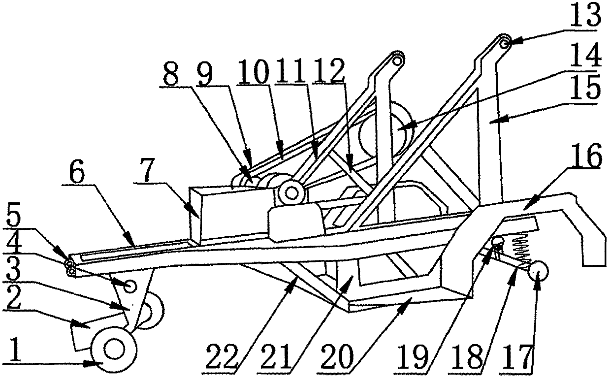
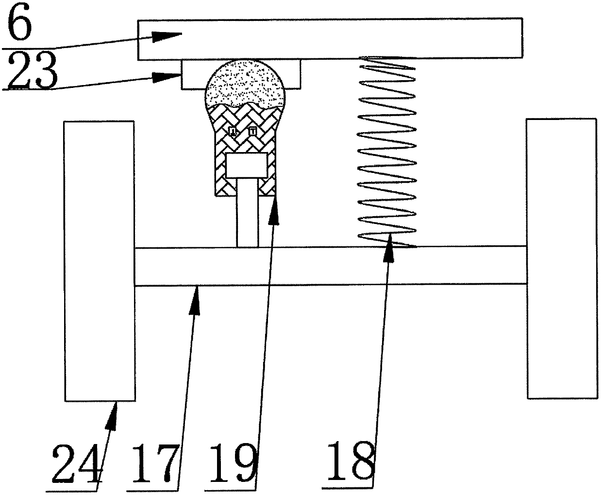
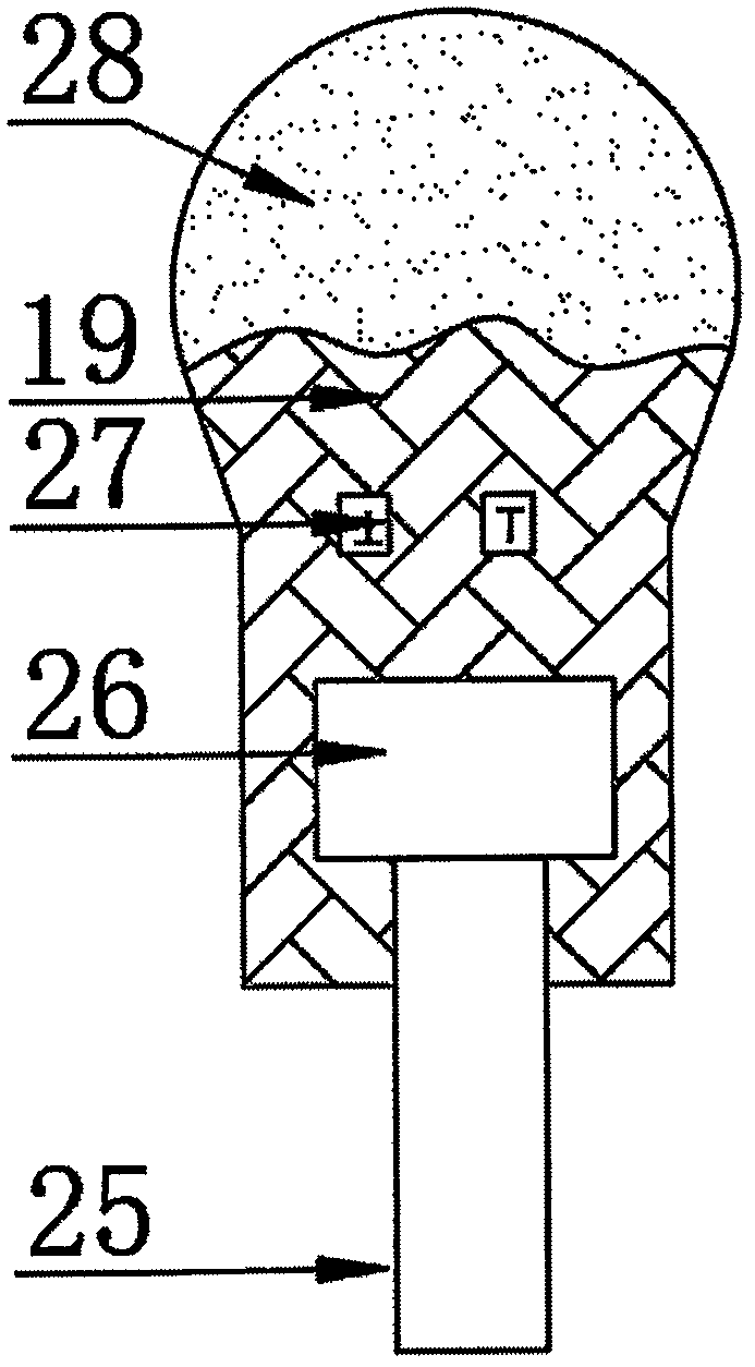
[0017] see Figure 1-3 , the present invention provides a technical solution: a draw frame for a tractor, including a front shaft 1, a head bracket 2, a connecting plate 3, a head connecting hole 4, a bolt hole 5, a main drawing plate 6, a seat 7, Wheel belt front axle disk 8, axle disk shell 9, tire belt 10, side bracket 11, horizontal bracket 12, farm tool connection hole 13, wheel belt rear axle disk 14, vertical bracket 15, rubber wheel shell 16, rear shaf...


PUM


Abstract

The invention discloses a draw frame for a tractor, which comprises a front rotating shaft, a head support, a connecting plate, a machine head connecting hole, a bolt hole, a main drawing plate, a seat, a wheel belt front axle disk, a axle disk shell, and a wheel belt , side brackets, horizontal brackets, connection holes for agricultural implements, rear axle discs with wheels, vertical brackets, rubber wheel housings, rear shafts, springs, shock absorbers, pedals, underframes, ribs, bosses and rubber wheels, all The main traction plate is connected with the front rotating shaft through the connecting plate, the chassis is installed on one side of the main traction plate, the reinforcing rib is connected with the rubber wheel shell through the pedal, and the rear frame is installed on the other side of the chassis. A shaft, one side of the rear shaft is embedded with a spring and a shock absorber, one side of the side bracket is welded with a vertical bracket, one side of the vertical bracket is welded with a horizontal bracket, and the tractor's traction frame is easy to use , with multi-directional stability, multi-hole connection, multi-tool assembly and shock absorber shock absorption functions, easy to use.

Description

technical field [0001] The invention relates to the technical field of traction frame equipment, in particular to a traction frame for a tractor. Background technique [0002] The traction device is attached to the back of the tractor, and the tractor power pulls the agricultural machinery that completes various operations. In order to meet the requirements of different implements and different operations, the traction point can be adjusted horizontally and vertically within a certain range of the traction plate. Compared with suspended and semi-suspended agricultural machinery, agricultural machinery has good stability and strong adaptability to ground conditions, but has poor maneuverability, large turning radius, and complex structure. operation, typically for large, wide or heavy agricultural machinery that cannot be accommodated by the tractor hitch. [0003] The existing draw frame does not have the functions of multi-directional stability, multi-hole connection, mult...

Claims


Application Information

Patent Timeline
IPC IPC(8): A01B59/042
CPCA01B59/042
Inventor 陈相贤杨毅坚
Owner GUANGXI HONGXING MACHINERY CO LTD
Learn More