Frisbee throwing device and frisbee throwing method

A technology of flying discs and launching racks, applied in the field of shooting competitions, can solve the problems of high cost, large volume, and inconvenient transportation, and achieve the effect of low cost, small volume, and convenient transportation

Pending Publication Date: 2018-04-03
SOUTH CHINA AGRI UNIV
View PDF5 Cites 2 Cited by
  • Summary
  • Abstract
  • Description
  • Claims
  • Application Information

AI Technical Summary

Problems solved by technology

However, at present, the Frisbee throwing machine mainly uses compressed gas to jet the Frisbee to launch the Frisbee. The Frisbee throwing machine using

Method used


Image

  • Frisbee throwing device and frisbee throwing method
  • Frisbee throwing device and frisbee throwing method
  • Frisbee throwing device and frisbee throwing method

Examples


Embodiment 1

[0034] This embodiment provides a frisbee throwing device, which uses the lifting method to transmit the frisbee, and uses the friction transmission to drive the frisbee to launch. It is not only small in size, quick in assembly, low in cost, and convenient in handling, but also easy to realize the frisbee Fixed point, positioning, fixed speed and continuous launch.

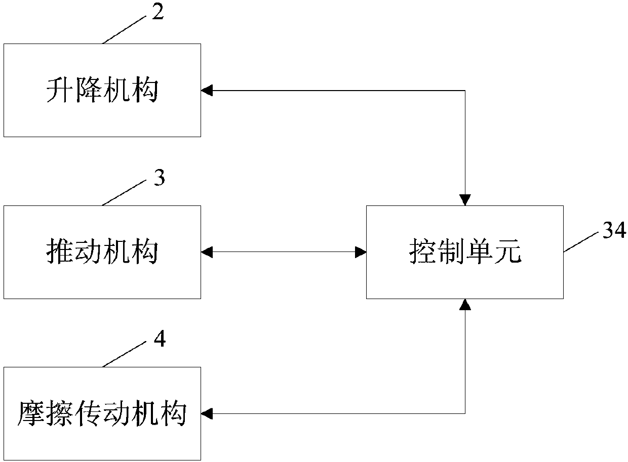
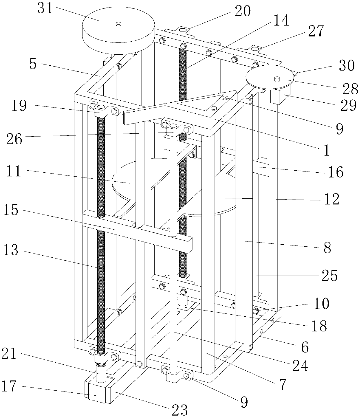
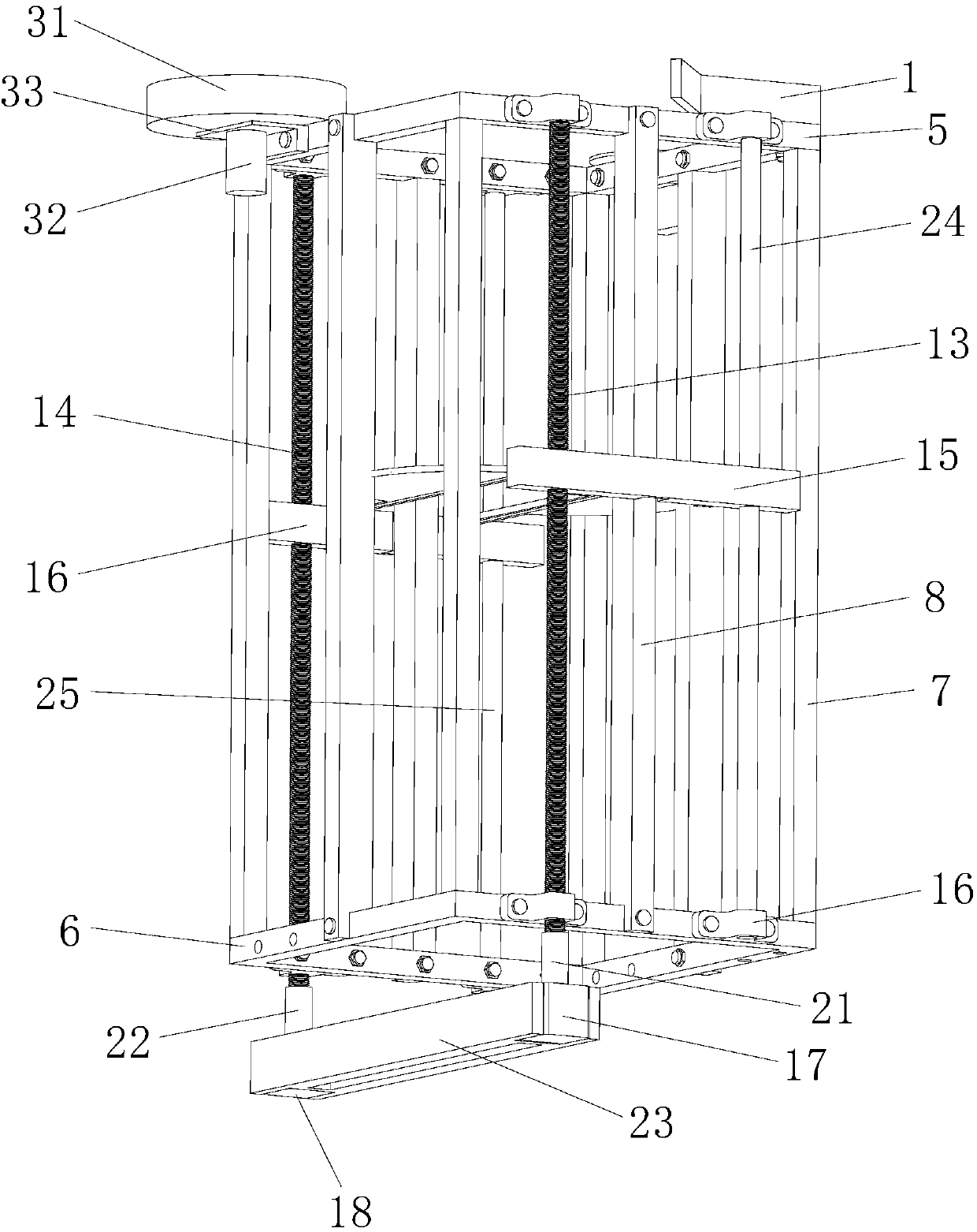
[0035] Such as Figure 1 ~ Figure 3 As shown, the flying disc projecting device of this embodiment includes a frame, a launching frame 1 , a lifting mechanism 2 , a pushing mechanism 3 and a friction transmission mechanism 4 .

[0036] The inside of the frame has an accommodating space for placing a flying disc, which can limit the displacement of the flying disc, which includes a first square frame 5, a second square frame 6 and four support columns 7, and the four support columns 7 are parallel to each other, the first square frame 5 and the second square frame 6 are arranged parallel to each other, and are pe...

Embodiment 2

[0059] The main features of this embodiment are: the support frame, lifting screw, lifting slider and lifting motor of the lifting mechanism 2 are all one, and the lifting screw and lifting slider are arranged on the front, rear, left or right of the frame. outside of the department. All the other are with embodiment 1.

Embodiment 3

[0061] The main features of this embodiment are: the frame is not provided with a fixed mount 8, the first lifting screw rod 13 is arranged at the middle position outside the front part of the frame, and the second lifting screw rod 14 is arranged at the middle position outside the rear part of the frame, The first lifting light bar 24 is arranged on the middle position outside the left part of the frame, and the second lifting light bar 25 is arranged on the middle position outside the right part of the frame. Since the positions of the lifting screw and the lifting light bar have changed, the first lifting slide Both the block 15 and the second lifting slider 16 are arranged in a bent structure. All the other are with embodiment 1.


PUM


Abstract

The invention discloses a frisbee throwing device and a frisbee throwing method. The device comprises a rack, a throwing frame, a lifting mechanism, a pushing mechanism and a friction transmission mechanism, wherein a containing space used for containing a frisbee is formed in the rack, the lifting mechanism is arranged on the rack and is used for driving the frisbee inside the rack to move to theupper end of the rack, the throwing frame, the pushing mechanism and the friction transmission mechanism are arranged at the upper end of the rack, the throwing frame is provided with a strip-shapedrail, the pushing mechanism is used for pushing the frisbee, the friction transmission mechanism is used for driving the frisbee pushed by the pushing mechanism to be thrown out along the strip-shapedrail direction of the throwing frame through friction transmission, and the lifting mechanism, the pushing mechanism and the friction transmission mechanism are connected with a control unit. The frisbee throwing device provided by the invention is small in size, rapid and convenient to assemble, low in cost, and convenient to carry, and the purpose of continuously throwing the frisbee in a fixed-point, fixed-position and fixed-speed manner is achieved.

Description

technical field [0001] The invention relates to a frisbee throwing machine, in particular to a frisbee throwing device and a frisbee throwing method. Belongs to the field of shooting competitions. Background technique [0002] The frisbee throwing machine is widely used in shooting competitions. It can realize fixed-point and positioning launching of frisbees, so that the shooting competition can be carried out efficiently and scientifically. However, at present, the Frisbee throwing machine mainly adopts the method of compressed gas jetting the Frisbee to realize the launch of the Frisbee. The Frisbee throwing machine using this type of launching method is relatively large in size, high in cost, and inconvenient to carry. , Low cost, easy to carry Frisbee throwing machine. Contents of the invention [0003] The purpose of the present invention is to solve the defects of the above-mentioned prior art, and provide a flying disc ejection device, which uses the lifting mode...

Claims


Application Information

Patent Timeline
IPC IPC(8): A63B67/06
CPCA63B67/06A63B2067/063
Inventor 漆海霞林森源闫国琦兰玉彬张志铭陈宇周靖康林圳鑫廖海
Owner SOUTH CHINA AGRI UNIV
Why Eureka
Try Eureka