
Robot executing mechanism

A technology of actuators and robots, which is applied in the direction of manipulators, object stacking, object destacking, etc., can solve the problems of influence, cost increase, bulkiness, etc., and achieve the effect of simple structure, reduced weight and cost, and low price

Pending Publication Date: 2018-04-03
SHENZHEN HYMSON LASER INTELLIGENT EQUIP CO LTD
View PDF0 Cites 0 Cited by
  • Summary
  • Abstract
  • Description
  • Claims
  • Application Information

AI Technical Summary

Problems solved by technology

The robot gripper uses the power source to make the gripper open and grip, and grips the material. Usually, the gripper has an independent power source in each direction of action, and the overall weight increases with the increase in the number of power sources. increase, the corresponding cost will also increase, and it is too bulky, which will affect the work to a certain extent

Method used


Image

  • Robot executing mechanism
  • Robot executing mechanism
  • Robot executing mechanism

Examples


Embodiment Construction

[0033] In order to make the object, technical solution and advantages of the present invention clearer, the present invention will be described in detail below in conjunction with the accompanying drawings and specific embodiments.

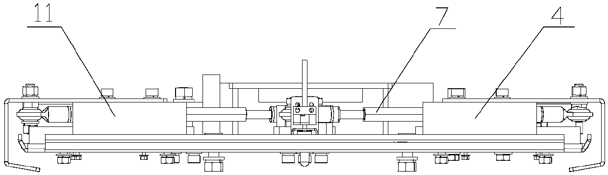
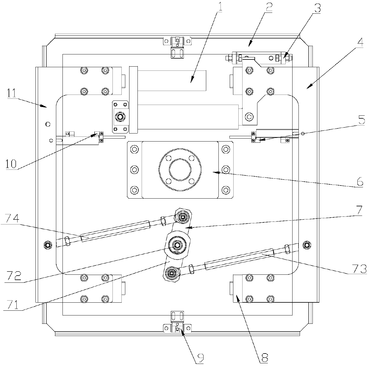
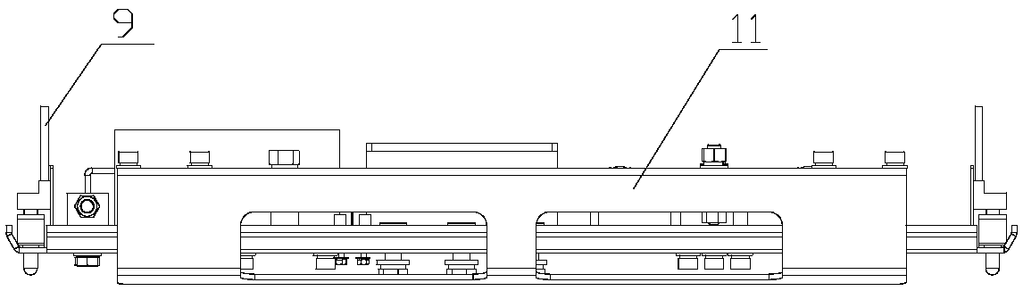
[0034] like Figure 1-3 As shown, a robot actuator provided by the present invention includes a linear drive mechanism, a base plate 2, gripper I 4, a link mechanism 7, a slide rail 8 and a gripper II 11, wherein the linear drive mechanism, the link mechanism 7 and The slide rail 8 is arranged on the base plate 2, the gripper I 4 and the gripper II 11 are slidably connected with the slide rail 8 and are located on opposite sides of the base plate 2, and the linkage mechanism 7 is located on the gripper I 4 and the gripper II 11, and connected with the gripper I 4 and the gripper II 11. The output end of the linear drive mechanism is connected with the gripper I 4 or the gripper II 11, and drives the gripper I 4 or the gripper II 11 to slide along...


PUM


Abstract

The invention relates to an executing mechanism, in particular to a robot executing mechanism. The robot executing mechanism comprises a linear driving mechanism, a base plate, a first clamping jaw, aconnecting rod mechanism, a sliding rail and a second clamping jaw. The linear driving mechanism, the connecting rod mechanism and the sliding rail are arranged on the base plate, and the first clamping jaw and the second clamping jaw are slidably connected with the sliding rail. The connecting rod mechanism is connected with the first clamping jaw and the second clamping jaw, and the output endof the linear driving mechanism is connected with the first clamping jaw or the second clamping jaw and drives the first clamping jaw or the second clamping jaw to slide along the sliding rail. Meanwhile, the connecting rod mechanism drives the second clamping jaw or the first clamping jaw to slide in the opposite direction along the sliding rail. The robot executing mechanism is a light robot gripper capable of protecting materials, and actions such as material clamping, carrying and stacking can be achieved.

Description

technical field [0001] The invention relates to an actuator, in particular to a robot actuator. Background technique [0002] With the rapid development of science and technology, automation equipment has made great progress in all walks of life. Robotic grasping replaces human labor in automated vaults, which can reduce costs and improve work efficiency. The robot gripper uses the power source to make the gripper open and grip, and grips the material. Usually, the gripper has an independent power source in each direction of action, and the overall weight increases with the increase in the number of power sources. increase, the corresponding cost will also increase, and it is too bulky, which will affect the work to a certain extent. Contents of the invention [0003] In view of the above problems, the object of the present invention is to provide a robot actuator. The mechanism is a light-duty, material-protecting robotic hand gripping structure, which can perform acti...

Claims


Application Information

Patent Timeline
IPC IPC(8): B25J15/08B25J19/02B65G61/00
CPCB65G61/00B25J15/08B25J19/02
Inventor 柳长庆蒋志东张振东穆松柏关士学谭国刚于吉生李健韩崇
Owner SHENZHEN HYMSON LASER INTELLIGENT EQUIP CO LTD
Features
  • Generate Ideas
  • Intellectual Property
  • Life Sciences
  • Materials
  • Tech Scout
  • Unparalleled Data Quality
  • Higher Quality Content
  • 60% Fewer Hallucinations
Learn More