Tensioning chain type conveyer

A chain conveyor and tensioning technology, which is applied in the field of conveying machinery, can solve problems such as poor coordination between the conveying pipe chain and the conveying pipe, reduced service life of the pipe chain conveyor, wear and tear of the conveying pipe chain and pipe chain sprockets, etc.

Pending Publication Date: 2018-04-03
JINGSU HUALIANG MACHINERY
View PDF11 Cites 1 Cited by
  • Summary
  • Abstract
  • Description
  • Claims
  • Application Information

AI Technical Summary

Problems solved by technology

Because the pipe chain conveyor has a closed conveying channel, it has been widely used in many occasions that require sealing, cleanliness, and environmental protection. However, the length of the conveying pipe chain and the length of the conveying pipeline must be Correspondingly, if the lengths of the two do not correspond, it will definitely affect the normal operation of the conveying pipe chain in the conveying pipeline, which will not only cause low conveying efficiency, but also cause a decrease in the service life of the pipe chain conveyor. The pipe chain conveyor can try to make the length of the conveying pipe chain correspond to the length of the conveying pipe during the manufacturing process, but aft

Method used


Image

  • Tensioning chain type conveyer
  • Tensioning chain type conveyer
  • Tensioning chain type conveyer

Examples


Embodiment Construction

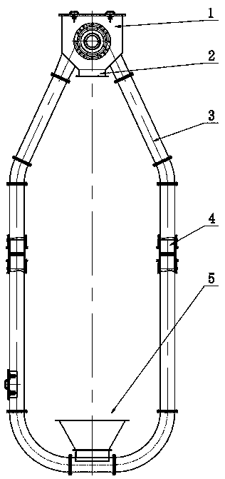
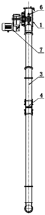
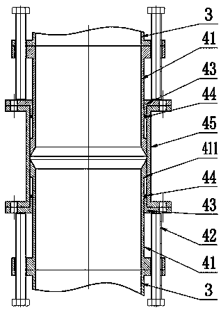
[0017] exist figure 1 and figure 2 In the shown tension chain conveyor, the conveying pipeline 3 is a channel for transporting materials with a circular cross-section, and the conveying pipeline 3 is provided with telescopic pipe joints 4, and the conveying pipe 3 provided with the telescopic pipe joints 4 is in an annular structure, A feed port 5 and a discharge port 2 are arranged on the conveying pipeline 3, and the two ends of the conveying pipeline 3 are connected through the drive box 1, and the drive box 1 is provided with a pipe chain drive sprocket 6, and the pipe chain drive sprocket 6 is connected to the drive The motor 7 is connected, and the driving motor drives the conveying pipe chain through the pipe chain drive sprocket 6 to run in the conveying pipe 3, and the conveying pipe chain will transport the material to be conveyed from the feed port 5 to the discharge port 2. The telescopic pipe joints 4 are arranged in pairs in the conveying pipeline 3, and the f...


PUM


Abstract

The invention discloses a tensioning chain type conveyor. The tensioning chain type conveyor comprises a conveying pipeline. The conveying pipeline is provided with a feed port and a discharge port. The two ends of the conveying pipeline communicate with each other through a drive box. The conveying pipeline is internally provided with extensible and retractable pipe joints which are arranged in pairs, the two extensible and retractable pipe joints which are arranged in pairs are arranged on the two sides of the drive box and are arranged in parallel. Each extensible and retractable pipe jointcomprises an outer sleeve, wherein the two ends of the outer sleeve are provided with extensible and retractable pipes in an insertion manner correspondingly, and an adjusting bolt is arranged between each extensible and retractable pipe and the outer sleeve. By adopting the tensioning chain type conveyor, tensioning between a pipe chain wheel and a conveying pipe chain can be kept conveniently,and the conveying pipe chain and the conveying pipeline can coordinate with each other well.

Description

technical field [0001] The invention relates to a conveying machine, in particular to a pipe chain conveying machine. Background technique [0002] Pipe chain conveyor is a continuous conveying equipment for conveying bulk materials such as powder, small granular and small blocks, which can be combined horizontally, inclined and vertically, and is widely used in fine chemicals, pesticide ores, building materials, food industry and other fields. The pipe chain conveyor uses the pipe chain scraper in the closed conveying pipeline as the conveying member to drive the material to move along the pipeline. The pipe chain scraper is installed on the conveying pipe chain, and the conveying pipe chain corresponds to the conveying pipe. The entire pipe chain conveys The machine forms an annular channel, and a material inlet and an outlet are arranged on the annular conveying channel. Because the pipe chain conveyor has a closed conveying channel, it has been widely used in many occa...

Claims


Application Information

Patent Timeline
IPC IPC(8): B65G23/44B65G23/22
CPCB65G23/22B65G23/44
Inventor 黄俊超史熙徐华进武珊珊申文平
Owner JINGSU HUALIANG MACHINERY
Why Eureka
Try Eureka