
DC magnetic biasing test device for transformer

A technology of DC bias and test equipment, applied in the direction of instruments, measuring electricity, measuring devices, etc., can solve the problems of potential safety hazards, inability to be universal, increase the iron loss and copper loss of transformers, etc., to improve the safety of use, design Clever, cost-saving effects

Active Publication Date: 2018-04-03
SIEMENS TRANSFORMER GUANGZHOU +1
View PDF10 Cites 2 Cited by
  • Summary
  • Abstract
  • Description
  • Claims
  • Application Information

AI Technical Summary

Problems solved by technology

DC bias is an abnormal working state of the transformer, which may have adverse effects on the transformer and the power grid, such as increasing the iron loss and copper loss of the transformer, increasing noise and vibration, and other damages
[0003] At present, the DC bias test circuit and related components of the transformer are all temporarily customized and built, which cannot be used universally, and there are potential safety hazards

Method used


Image

  • DC magnetic biasing test device for transformer
  • DC magnetic biasing test device for transformer

Examples


Embodiment Construction

[0036] In order to have a clearer understanding of the technical features, purposes and effects of the invention, the specific embodiments of the present invention are now described with reference to the accompanying drawings, in which the same reference numerals represent components with the same or similar structures but the same functions.

[0037] In this article, "schematic" means "serving as an example, example or illustration", and any illustration or implementation described as "schematic" should not be interpreted as a more preferred or more advantageous Technical solutions.

[0038] In order to make the drawing concise, each drawing only schematically shows the parts related to the present invention, and they do not represent the actual structure of the product. In addition, in order to make the drawings concise and easy to understand, in some drawings, only one of the components having the same structure or function is schematically shown, or only one of them is mar...


PUM


Abstract

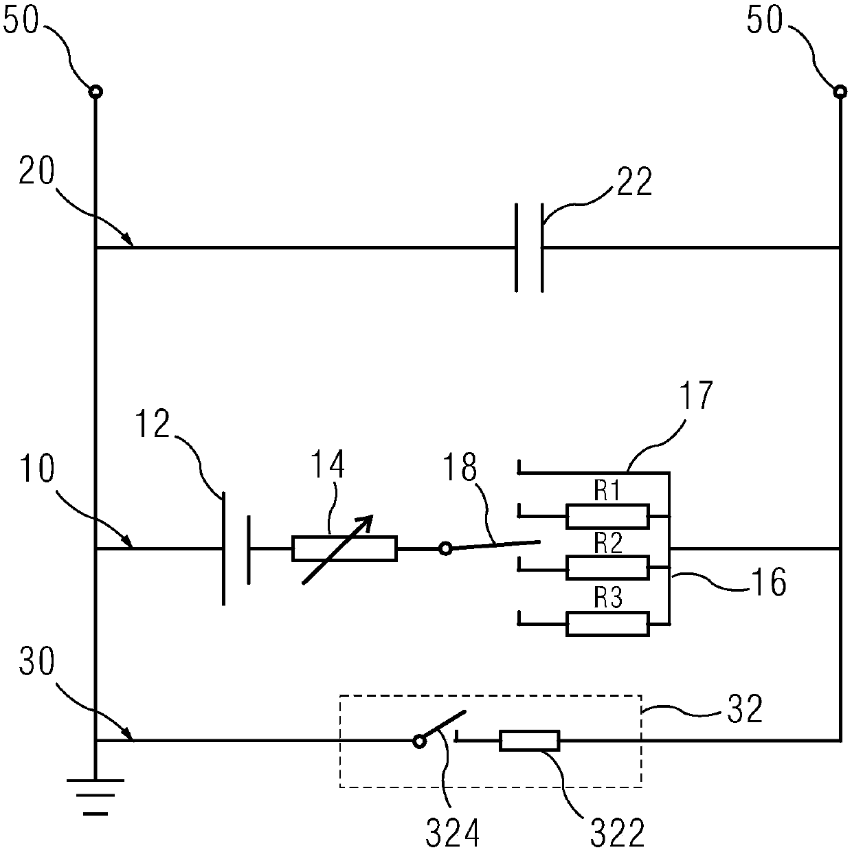
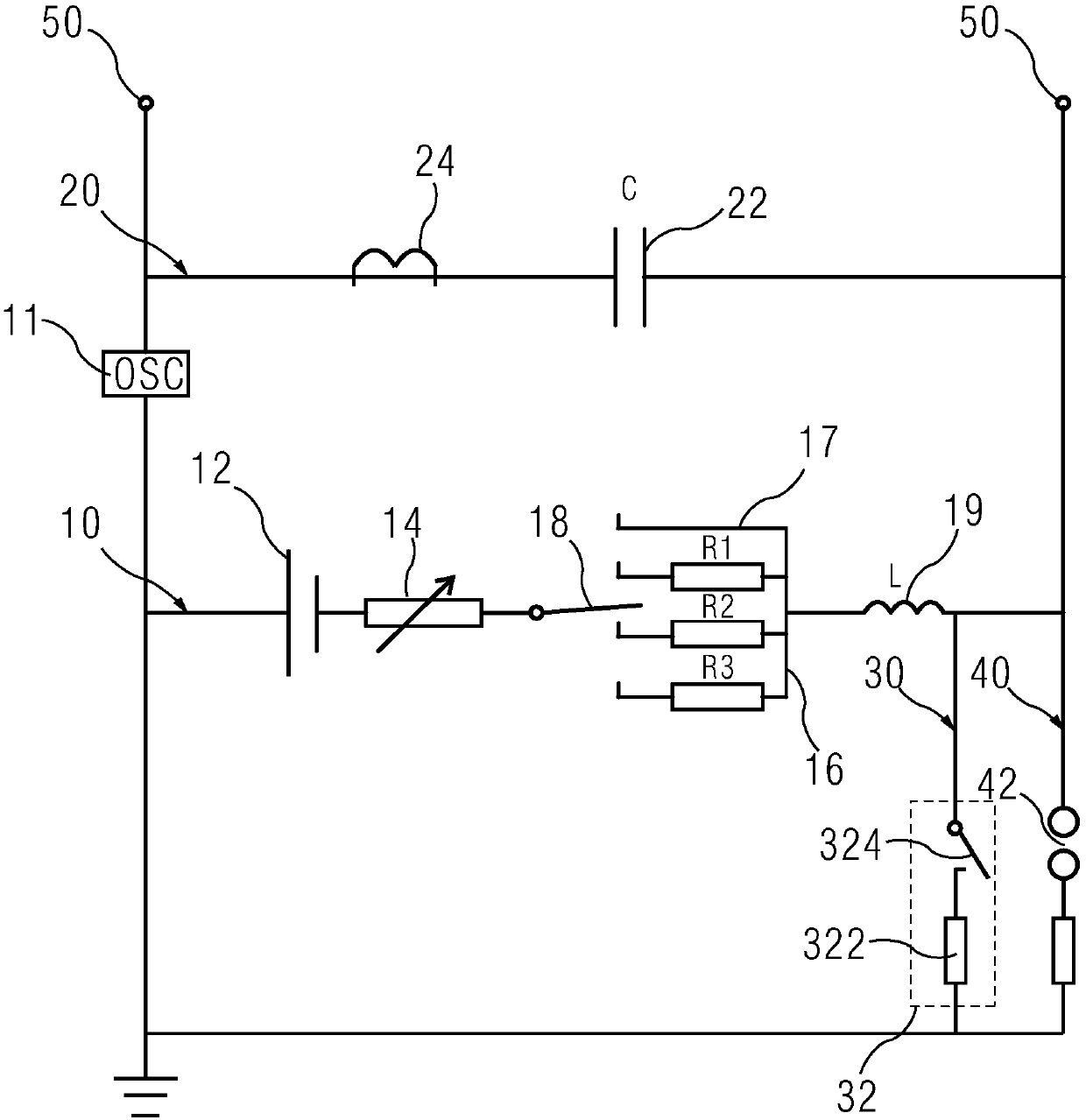
A DC magnetic biasing test device for a transformer is connected in series between a test transformer and a test device, and includes a DC branch, and an AC branch and a discharge branch that are connected in parallel to the DC branch. The DC branch delivers a DC current to the test transformer. The DC branch includes a DC power supply, a variable resistor, a resistor selection circuit, and a selection switch which are in series connection. The resistor selection circuit includes a plurality of regulation branches that are separately connected in series to the DC power supply. The selection switch can select one of the regulation branches to conduct the DC power supply. The AC branch includes a capacitor bank. The discharge branch includes a discharge element. After the DC power supply, the test transformer and the test device are powered off, the discharge element can conduct the discharge branch so as to be conducted with the AC branch, the test transformer and the test device. The discharge element can discharge the electrical energy of the capacitor bank, the test transformer and the test device.

Description

technical field [0001] The invention relates to a testing device, in particular to a DC bias testing device for a transformer. Background technique [0002] DC bias refers to the direct current or near direct current from the outside entering the transformer coil to excite the transformer, resulting in magnetic saturation of the transformer core for half a cycle, and a series of electromagnetic effects caused by it. DC bias is an abnormal working state of the transformer, which may have adverse effects on the transformer and the power grid, such as increasing the iron loss and copper loss of the transformer, aggravating noise and vibration, and other damages. [0003] At present, the DC bias test circuit and related components of the transformer are temporarily customized and built, which cannot be used universally, and there are potential safety hazards. Contents of the invention [0004] The purpose of the present invention is to provide a transformer DC bias test equip...

Claims


Application Information

Patent Timeline
Patent Type & Authority Applications(China)
IPC IPC(8): G01R31/00
CPCG01R31/00
Inventor 李林达杨家辉司代均吕晓东阮炜廖新征
Owner SIEMENS TRANSFORMER GUANGZHOU
Learn More