

Treatment device for crop seeds
A technology for seed treatment and crops, which is applied in the agricultural field, can solve the problems of prolonging the seed treatment cycle and long process transfer time, and achieve the effects of improving the seeding effect, shortening the treatment cycle, and reducing the treatment time
- Summary
- Abstract
- Description
- Claims
- Application Information
AI Technical Summary
Problems solved by technology
Method used
Image

Examples
Embodiment Construction
[0025] The content of the present invention will be described below in conjunction with specific embodiments.
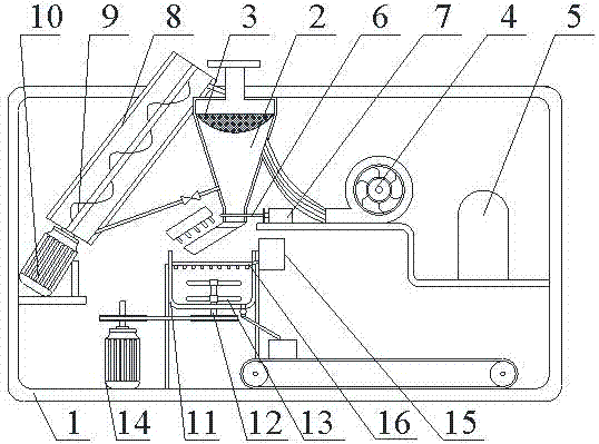
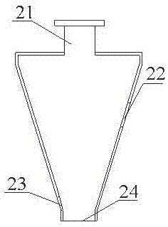
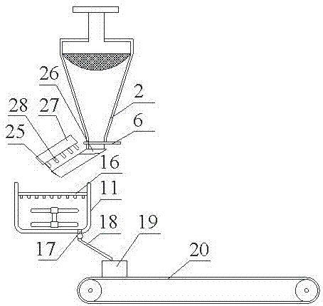
[0026] Such as Figure 1~3 as shown, figure 1 It is a structural schematic diagram of the crop seed treatment device proposed by the present invention; figure 2 yes figure 1 Schematic diagram of the structure of the part where the middle screening cylinder is located; image 3 yes figure 1 Schematic diagram of the part where the middle screening cylinder and mixing cylinder are located.
[0027] refer to Figure 1~3 , The crop seed treatment device includes: a frame 1 and a screening cylinder 2 connected to the frame 1, a return cylinder and a mixing cylinder.
[0028] The screening cylinder 2 is installed vertically on the frame 1, and the horizontal cross-sectional area of the screening cylinder 2 decreases gradually from top to bottom; the top of the screening cylinder 2 is provided with a feed inlet 21, and the middle part Separation port 22 is arranged...
PUM
 Abstract
Description
Claims
Application Information