
Fan spot welding fixture

A spot welding and fixture technology, used in welding equipment, manufacturing tools, auxiliary welding equipment, etc., can solve the problems of unstable welding quality of fan blades, low welding efficiency, and low degree of automation, so as to improve the degree of automation and production efficiency, The effect of reducing labor costs and high positioning accuracy

Active Publication Date: 2019-07-05
RES INST OF ZHEJIANG UNIV TAIZHOU
View PDF8 Cites 0 Cited by
  • Summary
  • Abstract
  • Description
  • Claims
  • Application Information

AI Technical Summary

Problems solved by technology

[0003] The purpose of the invention is to solve the technical problems of unstable welding quality of fan blades, low degree of automation and low welding efficiency

Method used


Image

  • Fan spot welding fixture
  • Fan spot welding fixture
  • Fan spot welding fixture

Examples


Embodiment Construction

[0027] The present invention will be further described below in conjunction with the accompanying drawings and specific embodiments.

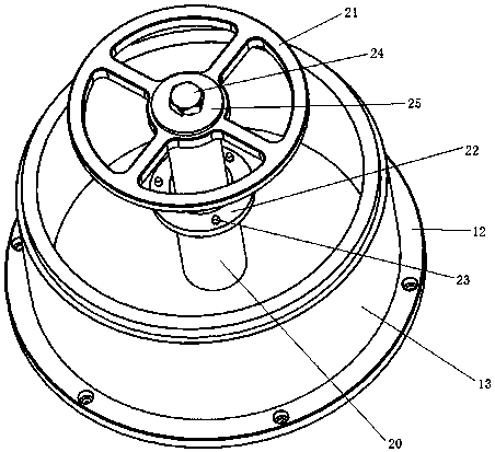
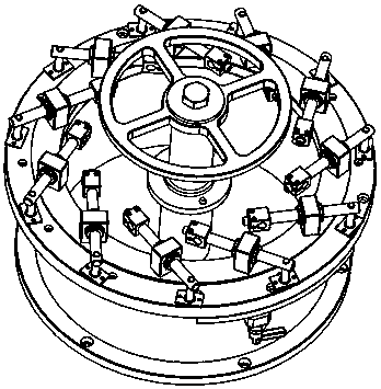
[0028] Such as Figure 1-10 As shown, the fan spot welding fixture of the present invention includes a base assembly and a central axis assembly;

[0029] The base assembly is welded by a round bottom plate 12 and a cylinder 13;

[0030] The central shaft assembly includes a central shaft 20 and a cover ring 21. The bottom of the central shaft 20 is vertically welded on the round bottom plate 12, and the cover ring 21 is detachably fixed on the top of the central shaft 20, such as by a combination of a washer 25 and a screw 24. , the middle part of the central axis 20 is fixed with a partition support plate 22, and a plurality of positioning pins 23 protruding from the upper surface of the partition support plate 22 are uniformly provided on the partition support plate 22;

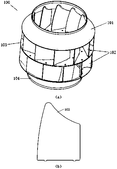
[0031] An inner ring 1 is fixed on the upper edge of the cylinder 13...


PUM


Abstract

The invention discloses a fan spot welding clamp. The fan spot welding clamp comprises a base assembly and a central shaft assembly; the base assembly is formed by welding a round bottom plate to a cylinder; the central shaft assembly comprises a central shaft and a cover ring; the bottom of the central shaft is perpendicularly welded to the round bottom plate; the cover ring is detachably fixed on the top of the central shaft; a partition supporting plate is fixed in the middle of the central shaft; a plurality of positioning pins which are projected out of the upper surface of the partitionsupporting plate are uniformly arranged on the partition supporting plate; an inner ring is fixed on the upper side of the cylinder along the periphery of the cylinder; an outer ring is mounted and isnext to the outer circle of the inner ring; the outer ring can rotate relative to the base; a knob plunger is mounted on the bottom surface of the inner ring; a plurality of positioning holes are formed in the bottom surface of the outer ring; the knob plunger is inserted in one of the positioning holes to position the outer ring; a plurality of rotating fingers are uniformly mounted and stretchacross the upper surface of the inner ring and the upper surface of the outer ring; the rotating fingers swing synchronously along with rotation of the outer ring; the number of the rotating fingers is the same as that of fan blades on one layer; and each rotating finger fixes the corresponding fan blade.

Description

technical field [0001] The invention relates to a fan spot welding fixture. Background technique [0002] The fan is welded by several workpieces, of which there are 11 blades on the upper and lower layers, a partition in the middle, a disc with holes in the middle, and an end cover on the upper and lower tops. At present, the positioning of workpieces such as fan blades before welding is manually positioned, and the position of the blades is easy to shift during the welding process, resulting in poor quality consistency after welding, and the automation of welding is low and the efficiency is low. Contents of the invention [0003] The purpose of the invention is to solve the technical problems of unstable welding quality, low degree of automation and low welding efficiency of fan blades at present. [0004] In order to achieve the purpose of the above invention, the present invention provides a fan spot welding fixture, including a base assembly and a central axis assem...

Claims


Application Information

Patent Timeline
Patent Type & Authority Patents(China)
IPC IPC(8): B23K37/04
CPCB23K37/0443
Inventor 武建伟孔丽微汪威威郑宣颜建国
Owner RES INST OF ZHEJIANG UNIV TAIZHOU
Features
  • Generate Ideas
  • Intellectual Property
  • Life Sciences
  • Materials
  • Tech Scout
  • Unparalleled Data Quality
  • Higher Quality Content
  • 60% Fewer Hallucinations
Learn More