
Device used for cleaning surface of petroleum pipeline

A surface cleaning device, oil pipeline technology, applied in grinding machines, metal processing equipment, grinding/polishing equipment, etc., can solve the problems of high time cost, long construction period, high operating intensity of construction personnel, etc., to improve work efficiency, The effect of quick cleaning and reducing labor intensity

Inactive Publication Date: 2018-04-06
CHENGDU DAMO PETROLEUM TECH CO LTD
View PDF7 Cites 9 Cited by
  • Summary
  • Abstract
  • Description
  • Claims
  • Application Information

AI Technical Summary

Problems solved by technology

[0002] The oil pipe will form a dirt layer and rust layer on the surface after use. During equipment maintenance, the oil pipe needs to remove the dirt layer and rust layer on the surface. The operation of the prior art is to use a manual hand-held grinder for grinding to remove the dirt. layer and rust layer removal, this method has the following disadvantages, the construction period is long, the operation intensity of the construction personnel is high, the efficiency is extremely low, the time cost of cleaning an oil pipe is high, and other auxiliary equipment is needed to help rotate the oil pipe, the construction environment Poor, because there are petroleum substances and rust substances on the surface of the used oil pipe, so when grinding, the high temperature and high-speed rotation will lift the rust dust into the air, and the construction workers will inhale the pollutants, which is extremely harmful to the construction personnel

Method used


Image

  • Device used for cleaning surface of petroleum pipeline
  • Device used for cleaning surface of petroleum pipeline
  • Device used for cleaning surface of petroleum pipeline

Examples


Embodiment

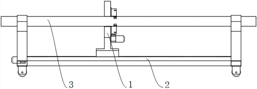
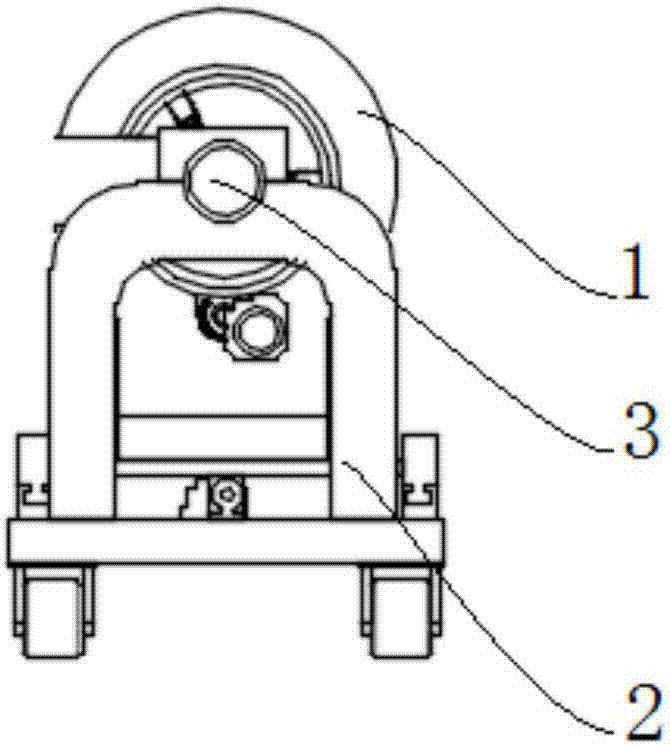
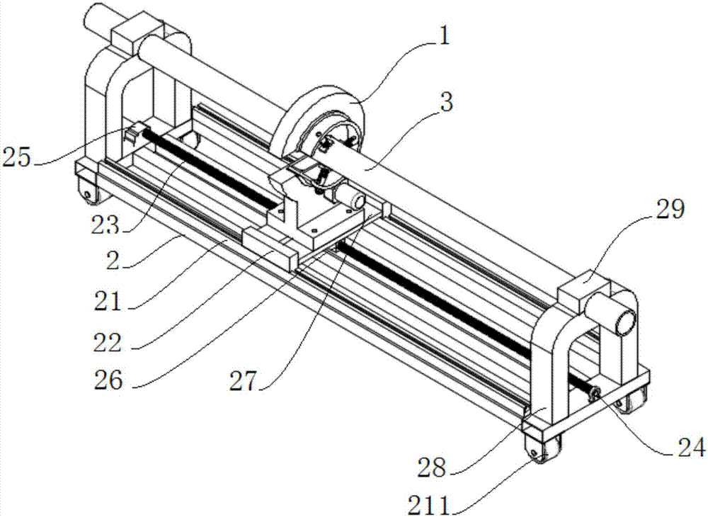
[0027] Such as Figure 1 to Figure 6 As shown, the present invention is used for oil pipeline surface cleaning device, comprises cleaning component 1, and described cleaning component comprises driving disc 11, motor 13, secondary gear 14, driven disc 12, grinding tool 128, and driving disc 11 is Disc-shaped, the drive disc 11 is provided with a first U-shaped notch 111, the first U-shaped notch 111 runs through both ends of the drive disc 11, the length of the first U-shaped notch 111 is greater than the radius of the drive disc 11, The first U-shaped notch 111 is left-right symmetrical along the centerline of the driving disk 11 . One of the end faces of the drive disc 11 is provided with an annular notch 112, the annular notch 112 is concentric with the drive disc 11, the drive disc 11 is provided with a mounting bracket 115, and the driven disc is installed in the annular notch 112 of the drive disc 11. 12. The limit ring 15 fixes the driven disc 12 in the annular notch 1...


PUM


Abstract

The invention discloses a device used for cleaning the surface of a petroleum pipeline. The device comprises a cleaning assembly. The cleaning assembly comprises a driving disc, a motor, a second-level gear, a driven disc and a grinding tool. The driving disc is in a disc shape. A first U-shaped notch is formed in the driving disc. An annular notch is formed in one end face of the driving disc andis concentric with the driving disc. The driven disc is installed in the annular notch of the driving disc. The driven disc comprises a round pipe body and gear teeth. A notch is formed between the outer circle and the inner circle of the round pipe body, and the multiple gear teeth are evenly distributed on the circumference of the surface of the outer circle of the round pipe body. The gear teeth of the driven disc are in engaged transmission with the second-level gear, and the second-level gear is connected with the driving disc in a pivotal manner. A motor is fixedly connected with the driving disc, and a first-level gear is arranged on a rotor output shaft of the motor. The first-level gear and the second-level gear are in engaged transmission. The grinding tool is arranged in the round pipe body of the driven disc. By means of the device, the working efficiency is improved, the manual labor intensity is lowered, and construction personnel do not need to conduct operation on thefield.

Description

technical field [0001] The invention relates to the technical field of petroleum equipment, in particular to a surface cleaning device for petroleum pipelines. Background technique [0002] The oil pipe will form a dirt layer and rust layer on the surface after use. During equipment maintenance, the oil pipe needs to remove the dirt layer and rust layer on the surface. The operation of the prior art is to use a manual hand-held grinder for grinding to remove the dirt. layer and rust layer removal, this method has the following disadvantages, the construction period is long, the operation intensity of the construction personnel is high, the efficiency is extremely low, the time cost of cleaning an oil pipe is high, and other auxiliary equipment is needed to help rotate the oil pipe, the construction environment Poor, because there are petroleum substances and rust substances on the surface of the oil pipe after use, so when grinding, the high temperature and high-speed rotati...

Claims


Application Information

Patent Timeline
Patent Type & Authority Applications(China)
IPC IPC(8): B24B27/033
CPCB24B27/033
Inventor 贺昶明
Owner CHENGDU DAMO PETROLEUM TECH CO LTD
Learn More