
A train pantograph loss detection and protection device and method

A protection device and pantograph technology, applied in the field of rail transit, can solve problems affecting key components in the train traction system

Active Publication Date: 2019-11-12
CSR ZHUZHOU ELECTRIC LOCOMOTIVE RES INST
View PDF8 Cites 0 Cited by
  • Summary
  • Abstract
  • Description
  • Claims
  • Application Information

AI Technical Summary

Problems solved by technology

[0013] In view of this, the purpose of the present invention is to provide a train pantograph power failure detection and protection device and method, which can solve the problem that existing solutions easily cause the corresponding equipment in the train traction system to withstand voltage or current beyond the normal range in a short time , thus affecting the technical problems of the service life of key components in the train traction system, such as capacitors, reactors, motors, etc.

Method used


Image

  • A train pantograph loss detection and protection device and method
  • A train pantograph loss detection and protection device and method
  • A train pantograph loss detection and protection device and method

Examples


Embodiment 1

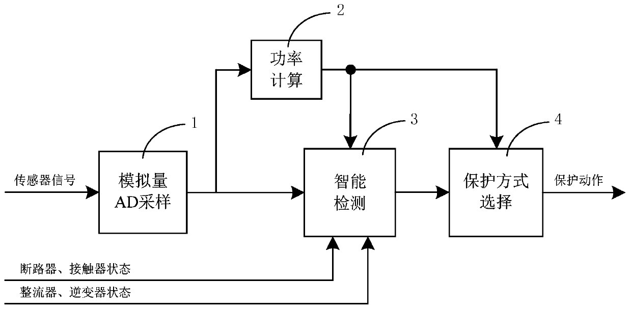
[0105] as attached figure 2 As shown, a specific embodiment of a train pantograph power loss detection and protection device, including:

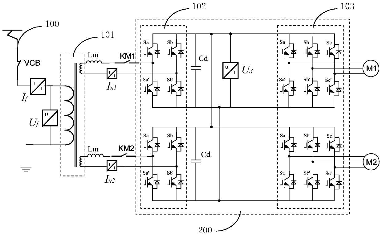
[0106] The analog quantity sampling unit 1 performs AD sampling on the voltage and current signals of the train traction system. The voltage and current signals sampled by the analog quantity sampling unit 1 include the network voltage synchronization signal U f , AC side current I of each rectifier n1 ~ I nX (X is determined by the multiplicity of the rectifier, as attached figure 1 The illustrated embodiment includes a rectifier-AC side current I n1 , rectifier two AC side current I n2 ), transformer primary side current I f , DC voltage U d .

[0107] The power calculation unit 2 calculates the power of the converter according to the voltage and current signals sampled by the analog sampling unit 1 . The converter power is used for subsequent intelligent detection unit 3 and protection selection unit 4 . According to the volta...

Embodiment 2

[0158] A specific embodiment of a train pantograph power failure detection and protection method, comprising the following steps:

[0159] A) AD sampling is carried out to the voltage and current signals of the train traction system;

[0160] B) Calculate the power of the converter according to the voltage and current signals obtained by sampling;

[0161] C) According to the voltage and current signals obtained by sampling, the state of the circuit breaker and contactor, the state of the converter, and the calculated power of the converter, the power failure detection and judgment of the pantograph are carried out;

[0162] D) If it is detected that the pantograph loses power in the train traction system in the working state, take corresponding protection measures according to the calculated power of the converter.

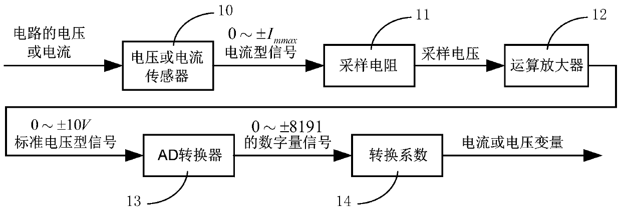
[0163] In step A), the voltage and current signals of the train traction system are sampled by the transmission control unit, and the voltage and current signal...


PUM


Abstract

The invention discloses a de-energizing detection and protection device and method for a pantograph of a train. The device includes an analog quantity sampling unit, a power calculation unit, an intelligent detection unit and a protection selection unit; the analog quantity sampling unit carries out sampling on voltage and current signals of a train traction system; the power calculation unit carries out power calculation on a current transformer according to the sampled voltage and current signals; the intelligent detection unit carries out de-energizing detection and judgement on the pantograph according to the sampled voltage and current signals, the states of a breaker, a contactor and the current transformer and the power value, obtain by the power calculation unit, of the current transformer; if the intelligent detection unit detects that the pantograph is de-energized under the working state of the train traction system, the protection selection unit takes corresponding protection measures separately according to the power value, obtained by the power calculation unit, of the current transformer. The de-energizing detection and protection device and method for the pantographof the train can solve the technical problem that by means of existing schemes, the service life of key components in the train traction system is influenced since corresponding equipment in the train traction system is likely to bear voltage or current exceeding a normal range in a short time.

Description

technical field [0001] The invention relates to the field of rail transportation, in particular to a train pantograph power failure detection and protection device and method applied in the railway industry. Background technique [0002] At present, the railway industry is booming, and thousands of electric locomotives or EMUs are operating on railway lines. Therefore, improving the ability of trains to deal with unexpected abnormal conditions has become an important guarantee for the safe and continuous operation of trains. Usually, when an electric locomotive or an electric multiple unit is running on a railway line, the train may encounter the following unexpected situations, which cause the traction system to fail to operate normally. [0003] One is that when the railway rail surface is not smooth, or the parallelism between the railway power supply network transmission line and the rail surface is poor, the pantograph-catenary separation phenomenon between the pantogr...

Claims


Application Information

Patent Timeline
IPC IPC(8): B60L3/00G01R31/00
CPCB60L3/0023B60L2240/40G01R31/008
Inventor 刘可安尚敬付刚张志学胡景瑜罗文广梅文庆章志兵陈志博彭赟
Owner CSR ZHUZHOU ELECTRIC LOCOMOTIVE RES INST
Learn More