Large-flow floor drain with observation window

An observation window and large flow technology, applied in waterway systems, drainage structures, water supply devices, etc., can solve the problems of small internal space, small flow, inconvenient maintenance, etc., to reduce the frequency of cleaning and the effect of large total flow

Inactive Publication Date: 2018-04-06
长春光速科技有限公司
View PDF3 Cites 0 Cited by
  • Summary
  • Abstract
  • Description
  • Claims
  • Application Information

AI Technical Summary

Problems solved by technology

[0008] In order to solve the problems of small internal space, small flow rate and inconvenient maintenance in existing floor drains, the present invention provides a large-flow floor drain with an observation window

Method used


Image

  • Large-flow floor drain with observation window
  • Large-flow floor drain with observation window

Examples


specific Embodiment approach 1

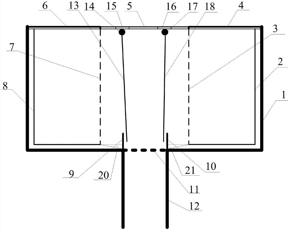
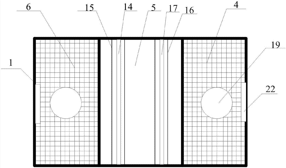
[0049] Such as figure 1 with figure 2As shown, a large-flow floor drain with an observation window of the present invention mainly includes: a casing 1, a second dirt bin 2, a second stainless steel mesh 3, a second upper cover 5, a first upper cover 6, and a first stainless steel mesh. Net 7, first dirt chamber 8, first dirt baffle plate 9, third stainless steel mesh 11, drainage pipe connecting hole 12, first water retaining sheet 13, first rotating shaft 14, first observation window 15, washing machine drain 19 , the first sedimentation tank 20, and the pulling port 22.

[0050] Grooves are arranged on the periphery of the upper edge of the casing 1 to facilitate fixing the upper cover.

[0051] The first loam cake 6 and the second loam cake 5 are all fixed on the top of the shell 1, the second loam cake 5 is a closed lid body, the first loam cake 6 has a water leakage hole, the first loam cake 6 and the second loam cake 5 adjacent to each other, the first upper cover 6...

specific Embodiment approach 2

[0061] Such as figure 1 with figure 2 As shown, a large-flow floor drain with an observation window of the present invention mainly includes: a casing 1, a second dirt bin 2, a second stainless steel mesh 3, a third upper cover 4, a second upper cover 5, a first upper cover Cover 6, first stainless steel mesh 7, first dirt bin 8, first dirt baffle 9, second dirt baffle 10, third stainless steel mesh 11, drainage pipe connection hole 12, first water baffle 13, first The rotating shaft 14, the first observation window 15, the second observation window 16, the second rotating shaft 17, the second water retaining sheet 18, the washing machine drain 19, the first sedimentation tank 20, the second sedimentation tank 21, and the lifting port 22.

[0062] Grooves are arranged on the periphery of the upper edge of the casing 1 to facilitate fixing the upper cover.

[0063] The first loam cake 6, the second loam cake 5 and the third loam cake 4 are all fixed on the top of the shell 1...


PUM


Abstract

A large-flow floor drain with an observation window relates to the field of floor drains and solves the problems of small internal space, small flow and inconvenient maintenance existing in the existing floor drains. The invention comprises: a shell; a first upper cover and a second upper cover fixed above the outer shell, the second upper cover is a closed cover, the first upper cover has a water leakage hole, and the first upper cover The cover and the second upper cover are arranged adjacent to each other; the first rotating shaft arranged at the junction of the first upper cover and the second upper cover or on the second upper cover; the first water retaining plate movably connected with the first rotating shaft; A drainpipe connection hole at the lower end of the shell and below the second upper cover; a first observation window arranged on the second upper cover and above the first rotating shaft. The invention is outside the drain pipe, has large space, large flow rate and convenient maintenance.

Description

technical field [0001] The invention relates to the technical field of floor drains, in particular to a large-flow floor drain with an observation window. Background technique [0002] The floor drain is an important interface connecting the drainage pipe and the indoor floor. As an important part of the drainage system in the residence, the performance of the floor drain directly affects the quality of the indoor air, and is very important for the odor control in the bathroom. [0003] At present, there is a kind of submarine floor drain, mainly including T-shaped automatic sealing four-proof floor drain, U-shaped double-sealed floor drain, V-shaped large-displacement sealed deodorant floor drain, copper horizon cleaning port, stainless steel cleaning port, clean floor drain, stainless steel floor drain And various shaped floor drains. [0004] At present, the submarine floor drain with relatively good sales volume on the market, the Chinese patent with the publication num...

Claims


Application Information

Patent Timeline
Patent Type & Authority Applications(China)
IPC IPC(8): E03F5/04
CPCE03F5/0407E03F5/041
Inventor 赵海慧
Owner 长春光速科技有限公司
Why Eureka
Try Eureka