Explosion-proof test system

A test system and special technology, applied in the direction of material explosion, can solve problems such as difficult operation, complex structure, and heavy movement process, and achieve the effect of convenient control and simple structure

Active Publication Date: 2018-04-06
绵阳海迪机器人科技有限公司
View PDF6 Cites 2 Cited by
  • Summary
  • Abstract
  • Description
  • Claims
  • Application Information

AI Technical Summary

Problems solved by technology

[0004] The inventor found that the existing equipment in the explosion-proof industry is complex in structure, difficult to operate, and the movement process is cumbersome, and cannot move in all directions. At the same time, th

Method used


Image

  • Explosion-proof test system
  • Explosion-proof test system
  • Explosion-proof test system

Examples


no. 1 example

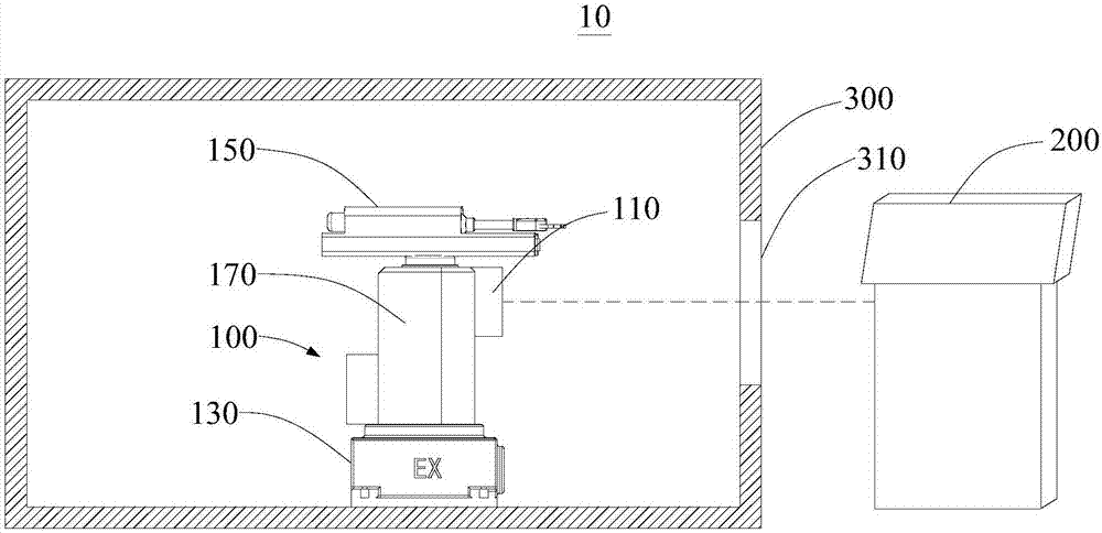
[0034] see in conjunction Figure 1 to Figure 2 , an explosion-proof test system 10, comprising a remote console 200, an explosion-proof chamber 300 and a special explosion-proof manipulator 100, the remote console 200 is arranged outside the explosion-proof chamber 300, the special explosion-proof manipulator 100 is accommodated in the explosion-proof chamber 300, and the explosion-proof chamber 300 A viewing window 310 is provided on the side wall.

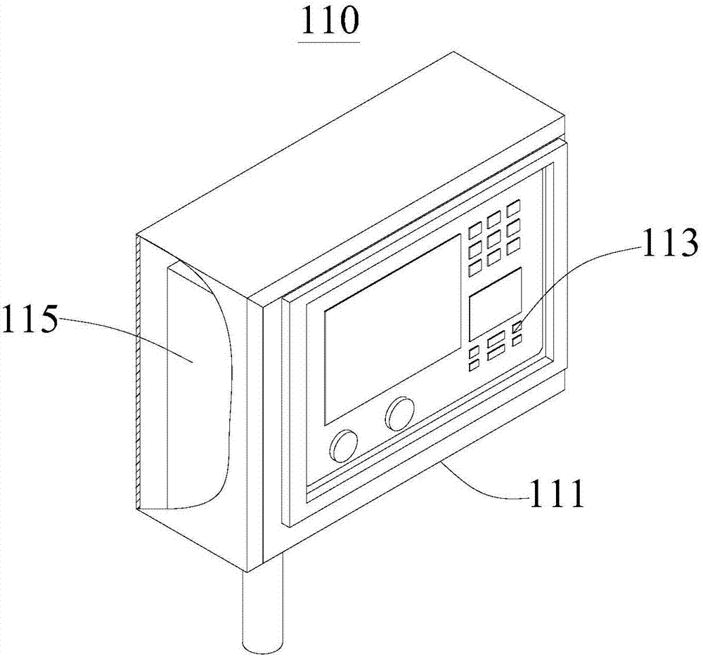
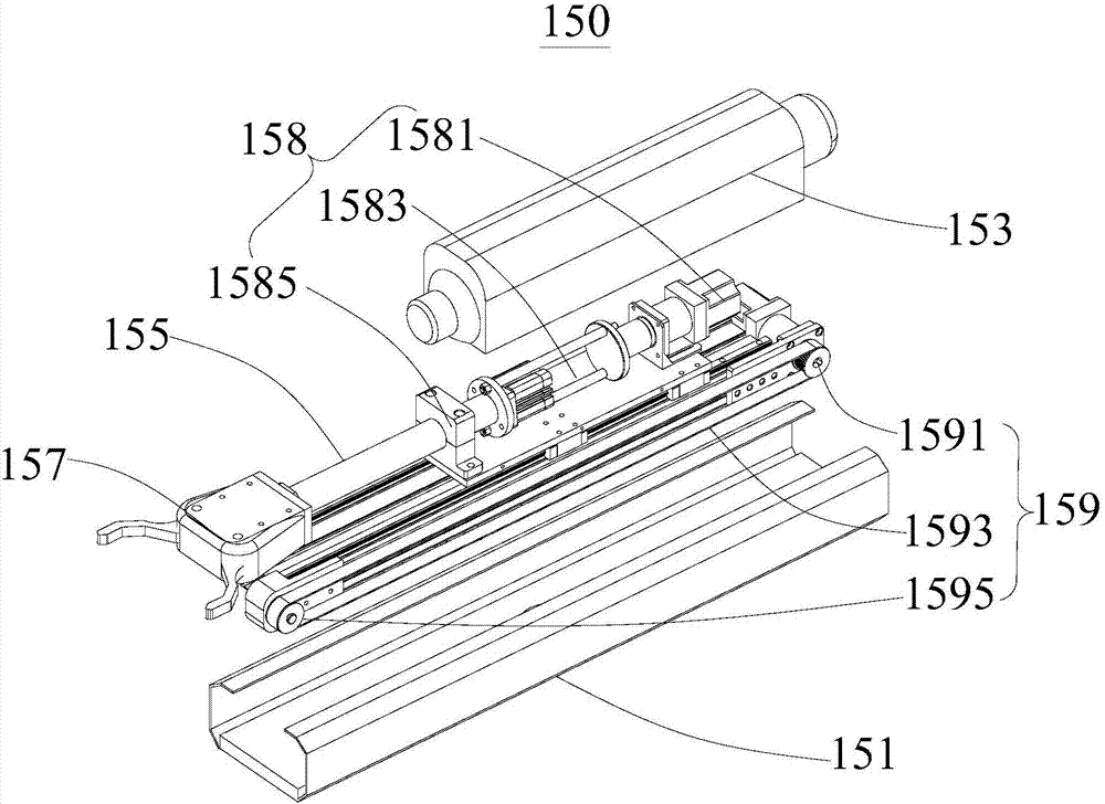
[0035] The special explosion-proof manipulator 100 includes an explosion-proof hand control box 110, an explosion-proof electrical base 130, a telescopic arm 150, a lifting rotating shaft 170 and a protective shell 190. The telescopic arm 150 is rotatably connected to the top of the lifting rotating shaft 170. Into the protective shell 190, the protective shell 190 is fixedly connected to the top of the explosion-proof electrical base 130, the explosion-proof manual control box 110 is fixedly connected to the protective shell 19...

no. 2 example

[0054] This embodiment provides an explosion-proof test system 10, whose basic structure, principle and technical effect are the same as those of the first embodiment. content. Compared with the first embodiment, the difference of this embodiment is that a power supply unit (not shown in the figure) is added.

[0055] The explosion-proof test system 10 includes a remote console 200, an explosion-proof room 300, a special explosion-proof manipulator 100, and a power supply unit. The remote console 200 and the power supply unit are all arranged outside the explosion-proof room 300. A viewing window 310 is provided on the side wall of the chamber 300 , and the power supply unit is electrically connected to the special explosion-proof manipulator 100 and the remote console 200 to supply power to the special explosion-proof manipulator 100 and the remote console 200 .

[0056] The special explosion-proof manipulator 100 includes an explosion-proof hand control box 110, an explosio...


PUM


Abstract

The invention provides an explosion-proof test system, and relates to the field of special explosion-proof equipment. The explosion-proof test system comprises a remote console, an explosion-proof room, and a special explosion-proof mechanical arm. The remote console is arranged out of the explosion-proof room and the special explosion-proof mechanical arm is arranged in the explosion-proof room.The lateral wall of the explosion-proof room is provided with an observation window. The special explosion-proof mechanical arm comprises an explosion-proof hand control box, an explosion-proof electrical base, a telescoping arm, an elevating rotation shaft, and a protective shell. The telescoping arm is rotatingly connected to the top end of the elevating rotation shaft. The other end of the elevating rotation shaft stretches into the protective shell. The protective shell is fixedly connected to the top of the explosion-proof electrical base. The explosion-proof hand control box is fixedly connected to the protective shell and is connected to the remote console through communication. The explosion-proof hand control box is electrically connected to the telescoping arm and the elevating rotation shaft. Compared with the prior art, the explosion-proof test system has a simple structure, moreover, the explosion-proof mechanical arm and the remote console are separated, the control is convenient, and the safety is enhanced at the same time.

Description

technical field [0001] The invention relates to the field of special explosion-proof equipment, in particular to an explosion-proof test system. Background technique [0002] For a long time, the country has stricter definitions of equipment design and manufacturing standards for the production environment of various explosives. In the design and manufacture of actual industrial equipment, pneumatic, hydraulic, and explosion-proof motors that meet the electrical certification indicators for explosive environments are mainly used as equipment power. However, in some production situations, precise and flexible motion control is required, that is, the development and manufacture of numerical control equipment based on the premise of explosion-proof safety has become the development trend of special industry equipment in the future. [0003] According to GB50058 "Code for Design of Power Installations in Explosion and Fire Hazardous Environments", my country's current standard e...

Claims


Application Information

Patent Timeline
IPC IPC(8): G01N25/54
CPCG01N25/54
Inventor 何坤
Owner 绵阳海迪机器人科技有限公司
Why Eureka
Try Eureka