Circular polarization probe antenna structure

An antenna structure and circular polarization technology, which is applied in the direction of antenna grounding switch structure connection, antenna grounding device, radiation element structure, etc., can solve the problems of small probe antenna size and high gain, so as to improve antenna gain and reduce antenna size , Improve the effect of polarization purity

Pending Publication Date: 2018-04-06
成都雷电微力科技股份有限公司
View PDF10 Cites 0 Cited by
  • Summary
  • Abstract
  • Description
  • Claims
  • Application Information

AI Technical Summary

Problems solved by technology

In the near-field test, the probe antenna is usually required to have small size, high gain, and convenient installation. It is difficult for conventional probe antennas to meet the above requirements at the same time.

Method used


Image

  • Circular polarization probe antenna structure
  • Circular polarization probe antenna structure
  • Circular polarization probe antenna structure

Examples


Embodiment 1

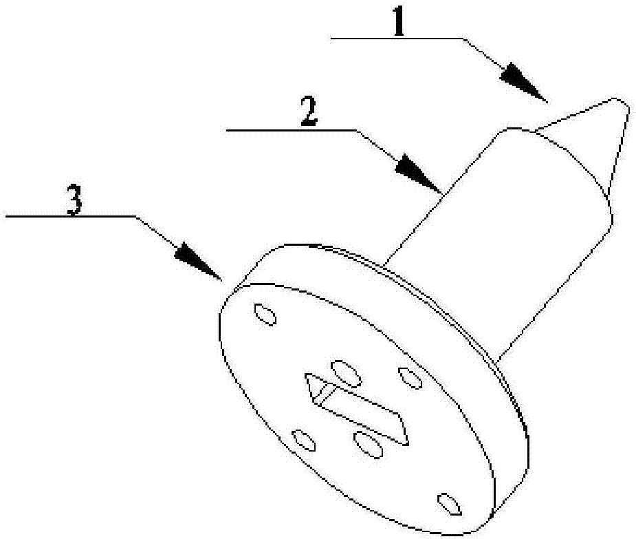
[0029] Embodiment 1: A circularly polarized probe antenna structure, comprising:

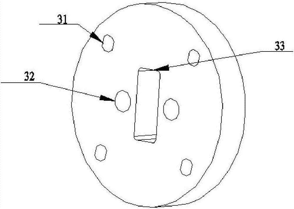
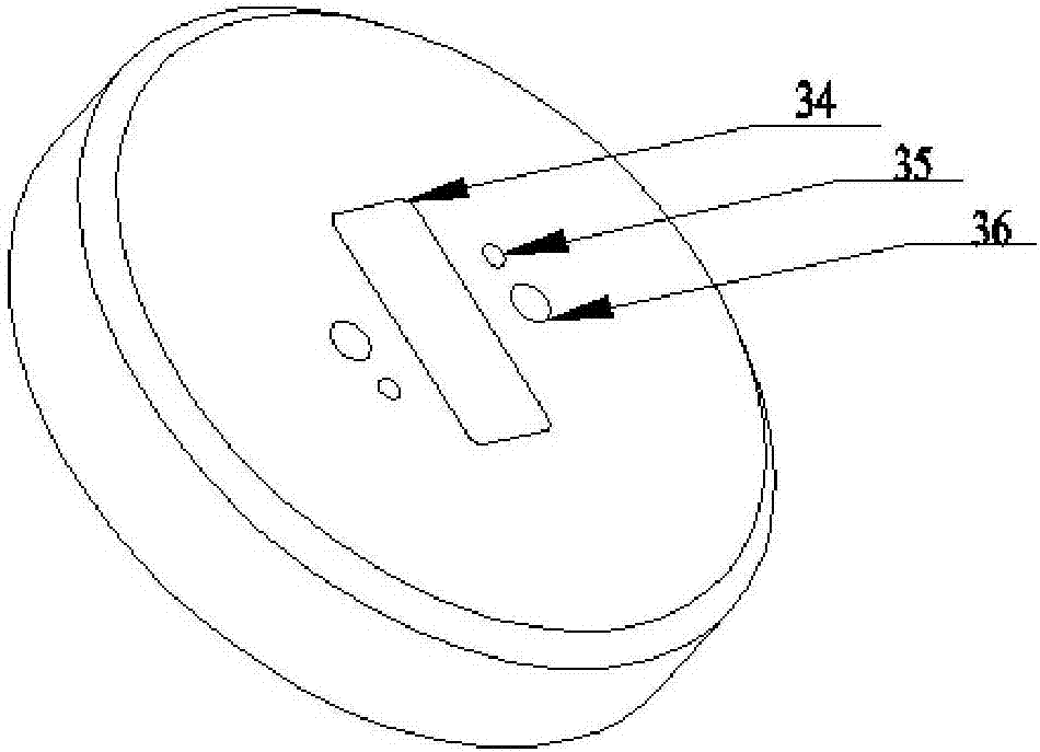
[0030] The power feeding part 3 , the power feeding part 3 is disc-shaped, and a rectangular waveguide 33 ( 34 ) is arranged in the center of the disc-shaped power feeding part 3 .

[0031] The metal shell 2 is wrapped around the cylindrical portion 15 and the waveguide stepped portion, and its internal space shape is completely matched with the 15 waveguide stepped portions of the cylindrical portion, and its shape is cylindrical.

[0032] The dielectric filling part 1 includes a conical frustum 11, a cylindrical part 15 and a waveguide step part connected in sequence; the waveguide step part includes at least two waveguide steps, and the top of the waveguide step part is provided with a rotating waveguide joint 14, and the rotating waveguide joint 14 and The shape of the rectangular waveguide 33 (34) is matched and inserted into the rectangular waveguide 33; the waveguide steps are more than t...


PUM


Abstract

The invention relates to the antenna design field, and especially relates to a circular polarization probe antenna structure comprising a feed portion, a metal housing, and a medium filling portion connected in order; the feed portion is in a disc type; a rectangular waveguide is arranged in the center of the disc type feed portion; the medium filling portion comprises a frustum, a cylinder portion and a waveguide step portion connected in order; the waveguide step portion comprises at least two waveguide steps; the top of the waveguide step portion is provided with a rotating waveguide segment; the rotating waveguide segment is matched in shape with the rectangular waveguide, and inserted in the rectangular waveguide; the metal housing wraps the cylinder portion and the waveguide step portion.

Description

technical field [0001] The invention relates to the field of antenna design, in particular to a circular polarization probe antenna structure. Background technique [0002] Probe antennas are mainly used in test sites for wireless products, such as near-field test systems, to calibrate the performance of the antenna under test, including gain, near-field amplitude and phase, pattern, sidelobe level, polarization purity, etc. . In the near-field test, the probe antenna is usually required to have small size, high gain, and convenient installation. It is difficult for conventional probe antennas to meet the above requirements at the same time. Contents of the invention [0003] The purpose of the present invention is to provide a miniaturized circularly polarized probe antenna with convenient use, simple installation, low cost and high gain for the special requirements of near-field testing. [0004] In order to achieve the above object, the technical scheme adopted in the...

Claims


Application Information

Patent Timeline
IPC IPC(8): H01Q1/36H01Q1/48H01Q1/50H01Q1/12
CPCH01Q1/12H01Q1/36H01Q1/48H01Q1/50
Inventor 肖润均张成王更生丁卓富
Owner 成都雷电微力科技股份有限公司
Why Eureka
Try Eureka