
Suspension type power distribution cabinet with convenience in height adjustment

A height-adjustable, suspended technology, applied in the substation/distribution device casing, electrical components, substation/switch layout details, etc., can solve the problem of inconvenient distribution line installation, undetermined suspension height, electrician maintenance and repair of electrical components Replacement troubles and other problems, to achieve the effect of easy adjustment, convenient electrician operation, easy to move up and down

Inactive Publication Date: 2018-04-06
SICHUAN LIZHI JIUCHUANG INTPROP OPERATION CO LTD
View PDF0 Cites 5 Cited by
  • Summary
  • Abstract
  • Description
  • Claims
  • Application Information

AI Technical Summary

Problems solved by technology

[0002] The power distribution cabinet is a commonly used equipment in the power distribution system. There are a large number of electrical components and power lines in the power distribution cabinet. In daily work, the maintenance, repair and replacement of electrical components are often carried out, and some equipment distribution is also required. For the installation of electric lines, most of the traditional power distribution cabinets are fixed at a specific position and cannot be moved. The commonly used hanging power distribution cabinets are directly fixed on the wall and cannot be moved, and the hanging height cannot be determined. During maintenance or installation, the height of the power distribution cabinet cannot be adjusted according to the situation, which is very troublesome for electricians to perform maintenance and replacement of electrical components, and it is very inconvenient to install power distribution lines, and the height of the suspension will also be very easy. Let the operator think that the personnel touch and view the distribution cabinet

Method used


Image

  • Suspension type power distribution cabinet with convenience in height adjustment
  • Suspension type power distribution cabinet with convenience in height adjustment

Examples


Embodiment Construction

[0016] All features disclosed in this specification, or steps in all methods or processes disclosed, may be combined in any manner, except for mutually exclusive features and / or steps.

[0017] Any feature disclosed in this specification, unless specifically stated, can be replaced by other alternative features that are equivalent or have similar purposes. That is, unless expressly stated otherwise, each feature is one example only of a series of equivalent or similar features.

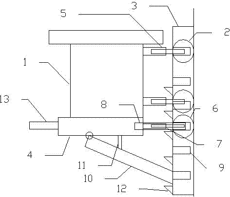
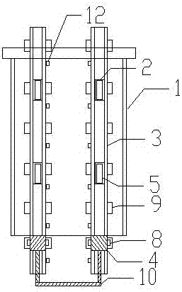
[0018] like figure 1 and figure 2 As shown, the present invention is a suspension type power distribution cabinet that is convenient for height adjustment, including a moving roller 2 arranged on the back wall of the cabinet body 1, and two chutes 3 arranged in parallel on the wall to cooperate with the moving roller 1 2 to roll , and two fixed plates 4 arranged in parallel at the bottom of the cabinet body 1 and consistent with the positions of the two chutes 3, the moving roller-2 is installed on...


PUM


Abstract

The invention discloses a suspended power distribution cabinet which is convenient for height adjustment. The power distribution cabinet includes a moving roller arranged on the back wall of the cabinet body, and two chutes arranged on the wall in parallel and capable of cooperating with the moving roller to roll. And two fixed plates parallel to the bottom of the cabinet and consistent with the positions of the two chutes, the end of the fixed plate close to the chute is provided with a moving roller 2, and the horizontal sides of the fixed plate are provided with fixed The two sides of the chute are provided with a number of slots that match the fixed inserting rods. A support frame is hinged between the two fixed plates, and a top is provided on the side of the support frame against the wall. frame, and several support seats are arranged on the chute. The invention can realize the free position movement of the suspended power distribution cabinet, facilitate the line installation and maintenance of the position adjustment of the suspended power distribution cabinet, and can also protect the power distribution cabinet to avoid random touch and inspection by personnel other than operators Distribution Cabinet.

Description

technical field [0001] The invention relates to a power distribution cabinet, in particular to a suspended power distribution cabinet which is convenient for height adjustment. Background technique [0002] The power distribution cabinet is a commonly used equipment in the power distribution system. There are a large number of electrical components and power lines in the power distribution cabinet. In daily work, the maintenance, repair and replacement of electrical components are often carried out, and some equipment distribution is also required. For the installation of electric lines, most of the traditional power distribution cabinets are fixed at a specific position and cannot be moved. The commonly used hanging power distribution cabinets are directly fixed on the wall and cannot be moved, and the hanging height cannot be determined. During maintenance or installation, the height of the power distribution cabinet cannot be adjusted according to the situation, which is ...

Claims


Application Information

Patent Timeline
IPC IPC(8): H02B1/40H02B1/30
CPCH02B1/40H02B1/306
Inventor 舒春柳
Owner SICHUAN LIZHI JIUCHUANG INTPROP OPERATION CO LTD
Learn More