U-shaped steel bushing shed structure for roadway support

A roadway support and section steel technology, applied in tunnels, tunnel linings, shaft linings, etc., can solve problems such as increased roadway maintenance costs, non-uniform effects, and accelerated roadway damage, so as to reduce roadway maintenance costs and improve stability and support. The effect of strength

Pending Publication Date: 2018-04-10
GUIZHOU UNIV
View PDF2 Cites 0 Cited by
  • Summary
  • Abstract
  • Description
  • Claims
  • Application Information

AI Technical Summary

Problems solved by technology

Both of the above two patents provide methods for controlling the surrounding rocks of relatively broken and soft rock roadways in the deep part, but the former does not carry out anchor net spraying after digging roadways, but directly drills bolt holes for bolt support, which is first of all An anchor cable extrusion reinforcement arch is not formed, which will lead to weak support strength and weak surface protection ability, and secondly, this will further weather and deliquesce the surrounding rock, so that the loads of the two sides of the roadway and the roof cannot be evenly acted on the support As a result, the phenomenon of stress concentration occurs, so that the rapid deformation of the surrounding rock and the collapse of the roof at the initial stage of roadway excavation cannot be effectively controlled, and finally the damage of the roadway is accelerated and the ideal effect cannot be achieved; the latter is not used. U-shaped steel is used for reinforcement and support, which will lead to a short maintenance time of the roadway, which will increase the maintenance cost of the roadway and generate unnecessary economic expenses.

Method used


Image

  • U-shaped steel bushing shed structure for roadway support
  • U-shaped steel bushing shed structure for roadway support

Examples


Embodiment

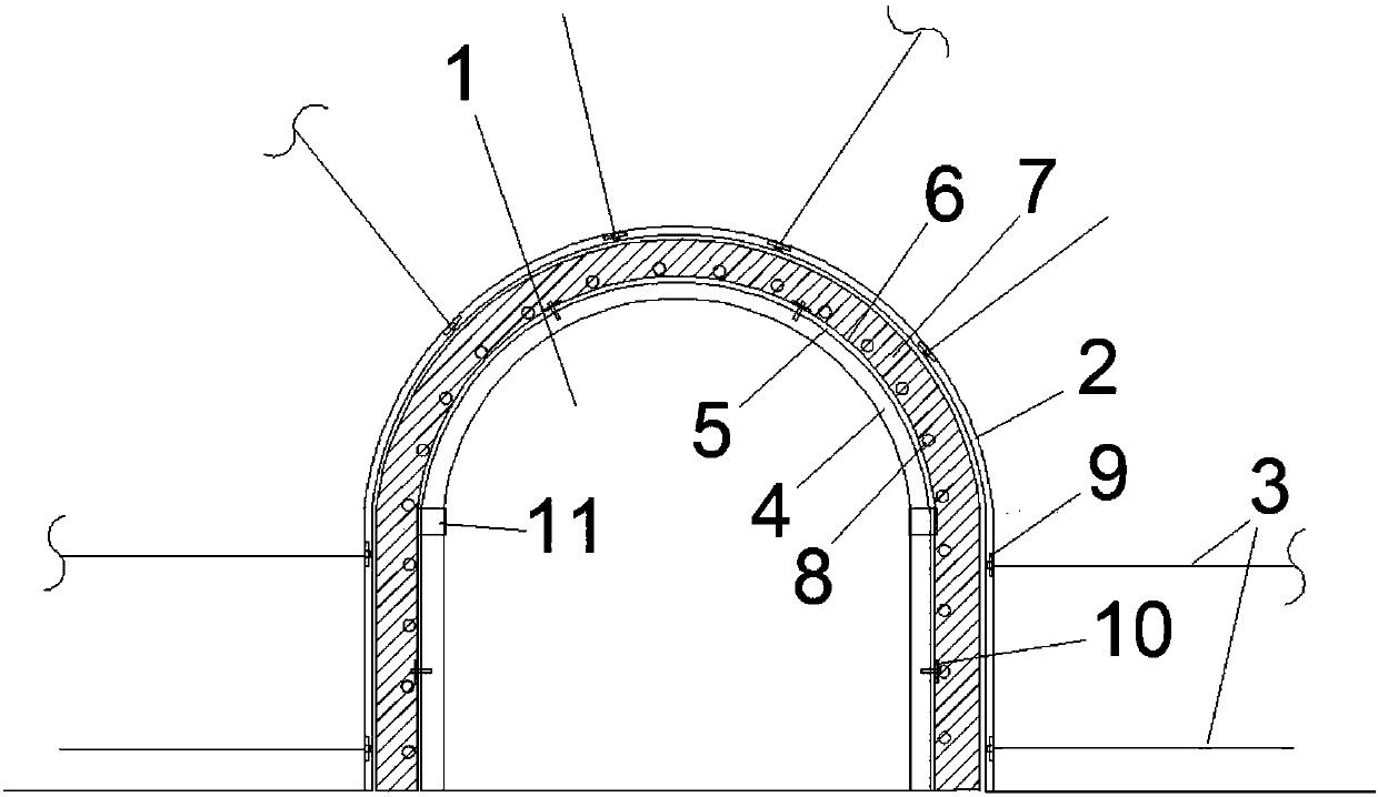
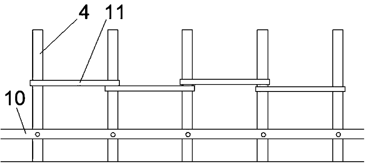
[0013] Refer to attached figure 1 and 2 , this embodiment provides a U-shaped steel shed structure for roadway support, including a metal mesh 2 hung on the surrounding rock surface of the roadway 1, and the metal mesh 2 is fixed on the surrounding rock surface of the roadway 1 through anchor cables 3, and the roadway The top plate and the surrounding rock of 1 are provided with anchor cable holes, one end of the anchor cable 3 is anchored in the surrounding rock through the anchor cable hole, and the other end is fixed on the inner side of the metal mesh 2 through the tray 9, and the inner side of the metal mesh 2 passes through the roadway. 1 Inverted U-shaped steel 4 sets of shed support with matching cross-sections, U-shaped steel 4 is arranged at equal intervals along the length direction of the roadway 1, and U-shaped steel 4 is fixedly connected by connecting rods 10, and two adjacent U-shaped steel 4 The connection between them is strengthened by the clamp cable 11, t...


PUM


Abstract

The invention discloses a U-shaped steel bushing shed structure for roadway support. A metal net is fixed on the roadway surrounding rock surface through anchor cables; the inner side of the metal netrealizes bushing shed support through reverse U-shaped steel matched with the roadway cross section; the U-shaped steel is arranged at equal intervals in the length direction of the roadway; the U-shaped steel is fixedly connected through clamp cables or connecting rods; a steel bar net is arranged at the outer side of the U-shaped steel in a hanging way; linoleum is laid outside the steel bar net; concrete is poured between the linoleum and the roadway cross section; steel bars are poured in the concrete; the inner side is one surface facing to the roadway; and the outer side is one surfacefacing to the roadway. The structure has the advantages that the high-intensity compression resistance can be realized; the proper yielding can also be realized; the stability and the support intensity of cracked soft rock roadway surrounding rock are greatly improved; certain guarantee is provided for safety production of coal mine; meanwhile, a certain amount of roadway maintenance cost is alsoreduced for enterprises; great benefits are brought to the development of coal enterprises; and the U-shaped steel bushing shed structure can be popularized and used in a wide range.

Description

technical field [0001] The invention belongs to the technical field of roadway surrounding rock support in mining engineering, and relates to a roadway shed support structure. Background technique [0002] Studies have shown that the status of coal as the main energy source in my country will not change fundamentally for a long period of time in the future. With the depletion of shallow coal resources, the mining depth and mining intensity of coal mines continue to increase. The severe degree of mine pressure in soft rock roadway shows serious deformation and damage of soft rock roadway. The deep rock mass is in a complex mechanical environment of "three highs and one disturbance", which makes the surrounding rock stability of deep soft rock roadways in coal mines affected by multiple factors, and the problem of surrounding rock control is becoming increasingly prominent. Soft rock roadway support is still an important and complicated technical problem in mining and underg...

Claims


Application Information

Patent Timeline
IPC IPC(8): E21D11/10E21D11/15E21D11/18E21D11/38E21D20/00
CPCE21D11/10E21D11/107E21D11/152E21D11/18E21D11/38E21D20/00
Inventor 左宇军刘镐马振乾席仕军孙文吉斌邬忠虎
Owner GUIZHOU UNIV
Why Eureka
Try Eureka