

High-voltage switch contact temperature detection and control system
A technology for detecting control systems and high-voltage switches, applied in radiation pyrometry, measuring devices, optical radiation measurement, etc. problem, to achieve the effect of convenient cooling
- Summary
- Abstract
- Description
- Claims
- Application Information
AI Technical Summary
Problems solved by technology
Method used
Image

Examples
Embodiment Construction
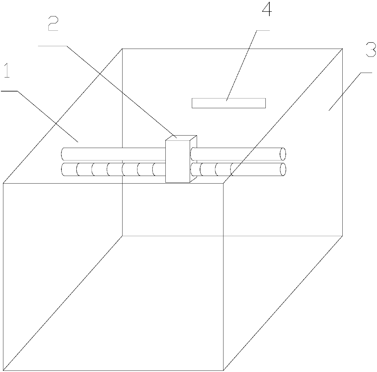
[0020] Specific embodiments of the present invention will be described in detail below in conjunction with the accompanying drawings. It should be understood that the specific embodiments described here are only used to illustrate and explain the present invention, and are not intended to limit the present invention.
[0021] In the present invention, unless stated otherwise, the used orientation words such as "up, down, left, right" usually refer to figure 1 Up and down and left and right are shown. "Inside and outside" refer to the inside and outside of the specific outline. "Far and near" refer to far and near relative to a certain component.
[0022] The invention provides a high-voltage switch contact temperature detection and control system, the high-voltage switch contact temperature detection and control system includes: a cooling mechanism, a control module, an infrared thermal imager and an image processing module, the infrared thermal imager and the high-voltage s...
PUM
 Abstract
Description
Claims
Application Information