Soil restoration cyclic drug mixing equipment

A soil remediation and recycling technology, applied in the field of soil remediation, can solve the problems of uneven mixing of remediation fluid and soil, insufficient remediation fluid content, limited remediation effect, etc., and achieves the effects of simple structure, improved mixing effect, and strong practicability.

Active Publication Date: 2018-04-13
南京园林建设集团有限公司
4 Cites 17 Cited by

AI-Extracted Technical Summary

Problems solved by technology

[0003] The use of chemical methods to repair soil means adding repair agents to it. The usual method is to crush the soil and spread it out, and spray the repair liquid on the upper surface. This method has the problem of uneven mixing of ...

Abstract

The invention discloses soil restoration cyclic drug mixing equipment. The soil restoration cyclic drug mixing equipment comprises a base, a smashing mixing box and a lifting mixing box. Rolling wheels facilitating transporting of the device are symmetrically arranged on the left side and the right side of the base correspondingly, the smashing mixing box and the lifting mixing box are arranged above the base, the outer sides of the smashing mixing box and the lifting mixing box are connected and fixed to the base through a first supporting column and a second supporting column, and a materialcharging channel is formed in the lower right side of the lifting mixing box. A material charging hopper is arranged at the upper end opening of the material charging channel, a driving motor is arranged above the lifting mixing box, and the driving motor is connected and fixed to the lifting mixing box through a motor stand. The soil restoration cyclic drug mixing equipment is simple and reasonable in structure and convenient to transport, materials are cyclically mixed between the smashing mixing box and the lifting mixing box, accordingly the mixing effect of the materials and a drug is greatly improved, the restoration effect on soil is ensured, and the practicality is high.

Application Domain

Technology Topic

Image

  • Soil restoration cyclic drug mixing equipment
  • Soil restoration cyclic drug mixing equipment
  • Soil restoration cyclic drug mixing equipment

Examples

  • Experimental program(1)

Example Embodiment

[0017] The technical solutions in the embodiments of the present invention will be clearly and completely described below in conjunction with the accompanying drawings in the embodiments of the present invention. Obviously, the described embodiments are only a part of the embodiments of the present invention, rather than all the embodiments. Based on the embodiments of the present invention, all other embodiments obtained by those of ordinary skill in the art without creative work shall fall within the protection scope of the present invention.
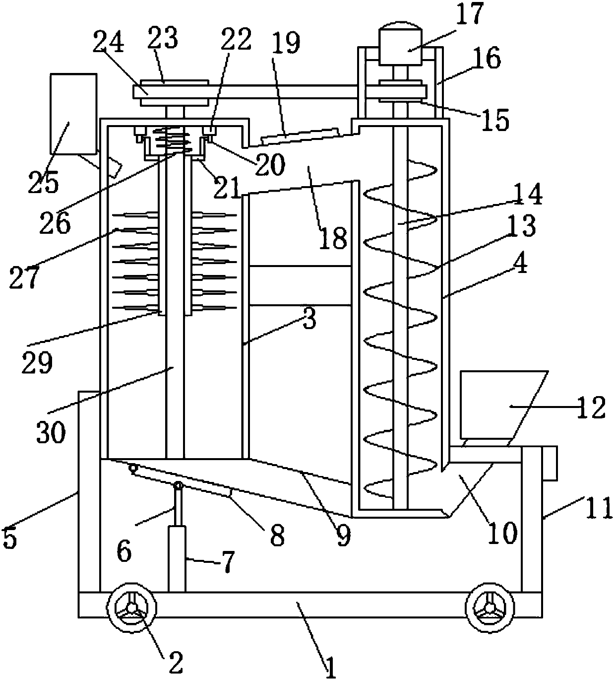
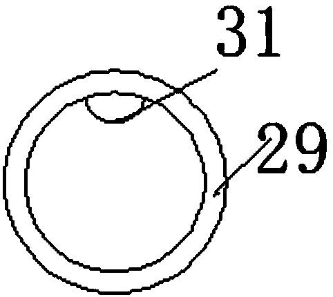
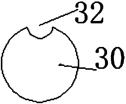
[0018] See Figure 1~4 In the embodiment of the present invention, a soil remediation circulating medicine mixing equipment includes a base 1, a crushing mixing box 3, and a lifting mixing box 4. The base 1 is provided with symmetrical rollers 2 on the left and right sides of the base 1 for convenient device transportation. For self-locking rollers, a crushing mixing box 3 and a lifting mixing box 4 are arranged above the base 1. The outsides of the crushing mixing box 3 and the lifting mixing box 4 are connected and fixed to the base 1 through the first support column 5 and the second support column 11 respectively. The crushing mixing box 3 and the lifting mixing box 4 are connected and fixed by a fixed rod. The lifting mixing box 4 is provided with a feeding channel 10 on the lower right side. The upper port of the feeding channel 10 is provided with a feeding hopper 12. The top of the box 4 is provided with a driving motor 17, which is connected and fixed to the lifting mixing box 4 through a motor frame 16. The output end of the driving motor 17 is provided with a lifting shaft 14 which passes through the top of the lifting mixing box 4 and is connected to the lifting The bottom of the mixing box 4 is rotatably connected. Both the top and the bottom of the lifting mixing box 4 are provided with fixed bearings that cooperate with the lifting shaft 4, and the lifting shaft 4 above the lifting mixing box 4 is provided with a driving pulley 15. A lifting blade 13 is provided outside the lifting shaft 4 inside the lifting mixing box 4, and a second guide channel 18 is provided between the discharge port on the upper left side of the lifting mixing box 4 and the feed port on the upper right side of the crushing mixing box 3. The left end of the second material guide channel 18 is lower than the right end, which facilitates the sliding of the material from the right end to the left end. The upper surface of the second material guide channel 18 is provided with an installation opening, and the installation opening is provided with an ultraviolet disinfection lamp 19 and the outside of the ultraviolet disinfection lamp 19 Equipped with a transparent protective cover, the ultraviolet disinfection lamp 19 is fixed on the second material guide channel 18 by bolts. The function of the ultraviolet disinfection lamp 19 is to disinfect and sterilize the materials passing through the second material guide channel 18. The upper end of the box 3 is provided with a rotating rod 30, and the upper end of the mixing box 3 is provided with a rotating bearing matched with the rotating rod 30. The upper end of the rotating rod 30 is provided with a driven pulley 23, which is one of the driven pulley 23 and the driving pulley 15 The rotating rod 30 inside the crushing mixing box 3 is provided with a sliding sleeve 29, and the sliding sleeve 29 is provided with a limiting protrusion 31. The surface of the rotating rod 30 is provided with a limiting protrusion 31. 31 is matched with the limiting groove 32, the cooperation of the limiting protrusion 31 and the limiting groove 32 prevents the relative rotation of the rotating rod 30 and the sliding sleeve 29. The sliding sleeve 29 is provided with a plurality of crushing knives 27, and the sliding sleeve The upper end of 29 is provided with L-shaped legs 21 symmetrically on both sides, and the upper end of the L-shaped legs 21 is provided with a pulley 20. The top of the crushing and mixing box 3 is provided with a supporting slide 22 that matches the pulley 20. There are six protrusions 33 distributed in the array, and the supporting slide rail 22 abuts against the pulley 20. The rotating rod 30 above the sliding sleeve 29 is provided with a fixed block 28. The fixed block 28 and the sliding sleeve 29 are connected and fixed by a return spring 26. , The discharging port at the bottom of the crushing mixing box 3 communicates with the lifting mixing box 4 through the No. 1 guide channel 9. The left end of the No. 1 guide channel 9 is higher than the right end, and the lower surface of the No. 1 guide channel 9 is provided with a bottom The feed opening and the unloading opening are matched with a movable bottom plate 8. The movable bottom The left end of the plate 8 is hinged with the No. 1 guide channel 9, the lower surface of the movable bottom plate 8 is hinged with a push-pull rod 6, the lower end of the push-pull rod 6 is hinged with the output end of the telescopic cylinder 7, and the lower end of the telescopic cylinder 7 is hinged on the base 1. When the device is working , The material is added to the lifting mixing box 4 through the feeding hopper 12 and the feeding channel 10. Driven by the driving motor 17, the lifting shaft 14 drives the lifting blade 13 to rotate, and then the material at the bottom of the lifting mixing box 4 is lifted up, and the material is carried After mixing, the materials enter the crushing mixing box 3 along the second guide channel 18, and the ultraviolet disinfection lamp 19 will disinfect and sterilize the materials passing through the second guide channel 18. The driving pulley 15 is driven by the lifting shaft 14. Will continue to rotate, the active 15 drives the driven pulley 23 to rotate through the transmission belt 24, the driven pulley 23 drives the rotating rod 30 to rotate, and then drives the sliding sleeve 29 to rotate, and the sliding sleeve 29 drives the crushing knife 27 to rotate, and then the The materials are crushed and mixed. When the sliding sleeve 29 rotates, the pulley 20 rotates along the supporting slide rail 22, so that the protrusion 33 on the supporting slide rail 22 will exert a force on the pulley 22, thereby pushing the sliding sleeve 29 along The rotating rod 30 slides down, and then cooperates with the reset function of the reset spring 26, so that the sliding sleeve 29 moves up and down along the rotating rod 30, which greatly increases the crushing area of ​​the crushing knife 27 and helps improve the material For the crushing effect, a drug box 25 is fixed on the upper left side of the crushing mixing box 3, and the drug box 25 drug delivery end extends into the crushing mixing box 3, and the feeding end is controlled by a solenoid valve, which is controlled by the solenoid valve to the crushing mixing box 3 Add medicament to realize the mixing of medicament and material. The preliminarily mixed material returns to the lifting mixing box 4 along the No. 1 guide channel 9, so that the cyclic mixing of the material can be realized. The solenoid valve, the drive motor 17 and The telescopic cylinder 7 is electrically connected to the control panel.
[0019] For those skilled in the art, it is obvious that the present invention is not limited to the details of the foregoing exemplary embodiments, and the present invention can be implemented in other specific forms without departing from the spirit or basic characteristics of the present invention. Therefore, from any point of view, the embodiments should be regarded as exemplary and non-limiting. The scope of the present invention is defined by the appended claims rather than the above description, and therefore it is intended to fall within the claims. All changes within the meaning and scope of equivalent elements of are included in the present invention. Any reference signs in the claims should not be regarded as limiting the claims involved.
[0020] In addition, it should be understood that although this specification is described in accordance with the implementation manners, not each implementation manner only includes an independent technical solution. This narration in the specification is only for clarity, and those skilled in the art should consider the specification as a whole The technical solutions in the embodiments can also be appropriately combined to form other implementations that can be understood by those skilled in the art.

PUM

no PUM

Description & Claims & Application Information

We can also present the details of the Description, Claims and Application information to help users get a comprehensive understanding of the technical details of the patent, such as background art, summary of invention, brief description of drawings, description of embodiments, and other original content. On the other hand, users can also determine the specific scope of protection of the technology through the list of claims; as well as understand the changes in the life cycle of the technology with the presentation of the patent timeline. Login to view more.

Similar technology patents

Classification and recommendation of technical efficacy words

  • Simple structure
  • Easy to carry

Beam expanding optical element, beam expansion method, image display apparatus, and head-mounted display

InactiveUS20070188837A1Reduce color unevennessSimple structureOptical light guidesSubstrate with hologramHead worn displayLight wave
Owner:KONICA MINOLTA INC

Microlithographic projection exposure apparatus

InactiveUS20050068499A1Simple structureReliable and low-maintenance operationProjectorsPhotomechanical exposure apparatusCamera lensPhysics
Owner:CARL ZEISS SMT GMBH

Display device

ActiveCN103914273AEasy to carryBig viewing screenDigital output to display deviceIdentification meansEngineeringFlexible display
Owner:BOE TECH GRP CO LTD

Treatments of therapy resistant diseases and drug combinations for treating the same

InactiveUS20080312199A1Accurately predict resistanceEasy to carryAntibacterial agentsBiocideCancers diagnosisMesothelioma
Owner:ORDWAY RES INST
Why Eureka
Try Eureka