Unlock instant, AI-driven research and patent intelligence for your innovation.
Multi-cylinder hydraulic forging machine and combined distribution of cylinders
What is Al technical title?
Al technical title is built by PatSnap Al team. It summarizes the technical point description of the patent document.
A hydraulic cylinder and forging machine technology, applied in the field of hydraulic cylinder arrangement and hydraulic forging machine, can solve problems such as energy loss, achieve the effects of reducing energy loss, unique design ideas, and fast pressure building speed
Inactive Publication Date: 2018-04-13
ZHONGKEJUXIN CLEAN ENERGY &HOT FORGING EQUIP RES & DEV CO LTD
View PDF8 Cites 2 Cited by
Summary
Abstract
Description
Claims
Application Information
AI Technical Summary
This helps you quickly interpret patents by identifying the three key elements:
Problems solved by technology
Method used
Benefits of technology
Problems solved by technology
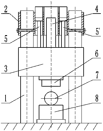
[0007] In order to solve the problem of energy loss caused by constant pressure when hydraulic forging machines independently provide power oil from accumulators, this invention proposes a multi-cylinder hydraulic forging machine and a combined arrangement of cylinders
Method used
Image
Click on the blue label to locate the original text in one second.
Reading with bidirectional positioning of images and text.
Examples
Embodiment 1
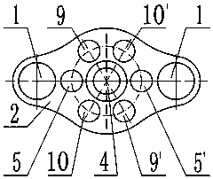
[0034] When the three groups of side hydraulic cylinders 5, 5' and 9, 9' and 10, 10' are evenly distributed on the circle centered on the central axis of the main hydraulic cylinder 4, and the three groups of side hydraulic cylinders 5, 5' and 9, 9 When the output pressure of ' and 10, 10' are the same, the combination is as follows:
[0036] b. Select two hydraulic cylinders as pressure cylinders for pressing down, and the option is any group of side hydraulic cylinders (such as: 5, 5' or 9, 9' or 10, 10');
[0037]c. Select three hydraulic cylinders as pressure cylinders for pressing down. Option 1 is to select any group of side hydraulic cylinders (such as: 5, 5' or 9, 9' or 10, 10') to combine with the main hydraulic cylinder 4, Option two is three side hydraulic cylinders whose central axis forms a regular triangul...
Embodiment 2
[0043] When the three groups of side hydraulic cylinders 5, 5' and 9, 9' and 10, 10' are randomly distributed on different circles with the central axis of the main hydraulic cylinder 4 as the center, and the three groups of side hydraulic cylinders 5, 5' and 9, When the output pressure of 9' and 10, 10' is different, the combination is as follows:
[0044] a. Select a hydraulic cylinder as the pressure cylinder for pressing down, and select the main hydraulic cylinder 4 as the working pressure cylinder;
[0045] b. Select two hydraulic cylinders as the pressure cylinders for pressing down, and the option is a group of side hydraulic cylinders (such as: 5, 5' or 9, 9' or 10, 10');
[0046] c. Select three hydraulic cylinders as the pressure cylinders for pressing down. The option is to select any group of side hydraulic cylinders (such as: 5, 5' or 9, 9' or 10, 10') to combine with the main hydraulic cylinder 4;
[0047] d. Select four hydraulic cylinders as the pressure cyli...
PUM
Abstract
The invention relates to a multi-cylinder hydraulic forgingmachine and combined distribution of cylinders. Different forging pressures are obtained through multi-cylinder distribution and different combinations of the hydraulic cylinders, through organic cooperation of multi-cylinder arrangement of the hydraulic forgingmachine and a valve control device, the situation that the hydraulic forgingmachine combines and distributes combined arrangement of the corresponding hydraulic cylinders according to the resistance magnitude is achieved, and the purpose that output pressure is matched with rolling resistance of a rolling machine is achieved. The problem of energy losses under the mode that an energy accumulator is adopted to independently provide power oil for the hydraulic forging machine is solved by the multi-cylinder hydraulic forging machine and combined distribution of the cylinders, and accordingly technical guarantees are provided for promotion of the mode that the energy accumulator provides the power oil for the hydraulic forging machine independently. The design thought is unique, the distribution variation of the hydraulic cylinders is large, the application range iswide, and the multi-cylinder hydraulic forging machine has the advantages that the pressure building speed is high, and energy is saved.
Description
technical field [0001] The invention relates to a hydraulic forging machine provided with a plurality of hydraulic cylinders, in particular to a method for arranging hydraulic cylinders when all or part of the hydraulic cylinders are in use, and belongs to the technical field of hydraulic transmission. Background technique [0002] Hydraulic forging machine is a new type of forging equipment. Due to its advantages of high automation, good control precision and saving raw materials, it is the first choice of high-end forging industry at home and abroad. It is widely used in machinery manufacturing and forging of high-quality and high-performance materials. At present, domestic better hydraulic forging machine components are designed and manufactured according to the international advanced level, and the key components are imported foreign famous brand products, so the equipment cost is very expensive. Due to the large energy consumption of the forging machinery, especially th...
Claims
Application Information
Patent Timeline
Application Date:The date an application was filed.
Publication Date:The date a patent or application was officially published.
First Publication Date:The earliest publication date of a patent with the same application number.
Issue Date:Publication date of the patent grant document.
PCT Entry Date:The Entry date of PCT National Phase.
Estimated Expiry Date:The statutory expiry date of a patent right according to the Patent Law, and it is the longest term of protection that the patent right can achieve without the termination of the patent right due to other reasons(Term extension factor has been taken into account ).
Invalid Date:Actual expiry date is based on effective date or publication date of legal transaction data of invalid patent.
IPC IPC(8): B21J9/12
CPCB21J9/12
Inventor 张连华赵永军马海军陈柏金
Owner ZHONGKEJUXIN CLEAN ENERGY &HOT FORGING EQUIP RES & DEV CO LTD

