Clamp structure for spraying welding of mouth mold cavity of glass mold

A technology of glass molds and dies, applied in the field of tooling and fixtures, can solve problems such as the impact of clamping efficiency, thickness consistency, and clamping troubles, and achieve the effect of ensuring uniform thickness, good level effect, and simple overall structure

Pending Publication Date: 2018-04-13
CHANGSHU JIANHUA MOLD TECH
View PDF19 Cites 16 Cited by
  • Summary
  • Abstract
  • Description
  • Claims
  • Application Information

AI Technical Summary

Problems solved by technology

This clamping method has at least the following disadvantages: First, because the clamping is troublesome, it affects the clamping efficiency and the final spray welding efficiency; It is difficult to ensure that it is in the desired horizontal state, but whether the level of the clamping die will affect the thickness consistency of the nickel-based al

Method used


Image

  • Clamp structure for spraying welding of mouth mold cavity of glass mold
  • Clamp structure for spraying welding of mouth mold cavity of glass mold
  • Clamp structure for spraying welding of mouth mold cavity of glass mold

Examples


Embodiment Construction

[0023] In order to understand the technical essence and beneficial effects of the present invention more clearly, the applicant will describe in detail the following examples, but the descriptions of the examples are not intended to limit the solutions of the present invention. Equivalent transformations that are only formal but not substantive should be regarded as the scope of the technical solution of the present invention.

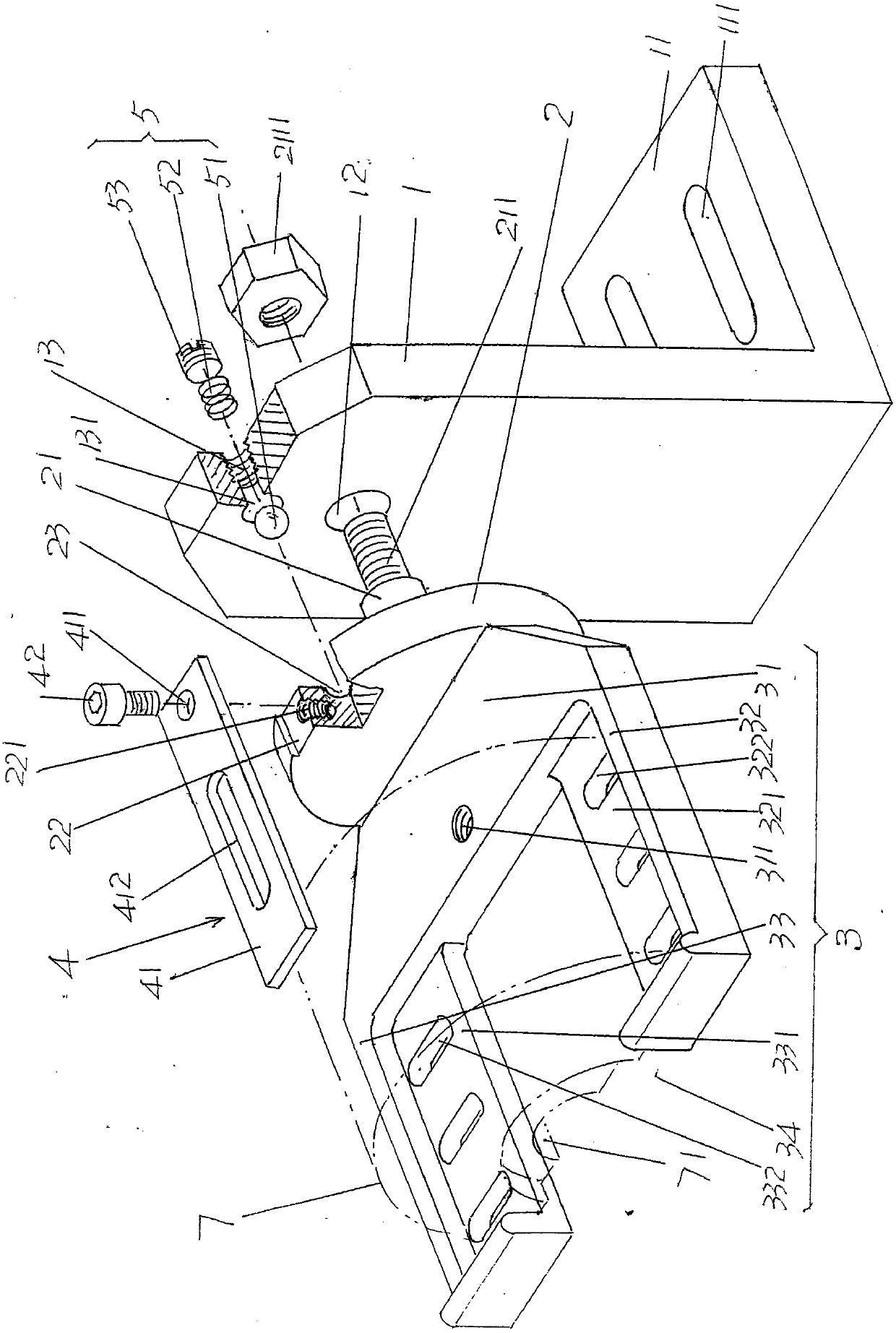
[0024] In the following descriptions, all concepts involving directionality or orientation of up, down, left, right, front and rear are aimed at figure 1 As far as the position and state of the present invention are concerned, it cannot be understood as a special limitation on the technical solution provided by the present invention.

[0025] See figure 1 , shows a support frame 1; shows a rotary plate 2, the rotary plate 2 is connected with the support frame 1 at a position corresponding to the upper left side of the aforementioned support frame 1; s...


PUM


Abstract

The invention relates to a fixture structure for spray welding of a glass mold die cavity, which belongs to the technical field of tooling and fixtures. It includes a support frame; a rotary plate, which is connected to the support frame at a position corresponding to the upper left side of the support frame; a die carrying platform, which is connected to the back of the rotary plate in a horizontal cantilever state. One side of the support frame is fixed; a die back positioning mechanism, which is connected to the rotary disk and stretches toward the direction of the die carrying platform in a horizontal cantilever state; a die carrying platform A horizontal holding mechanism, the die carrying platform horizontal holding mechanism is arranged on the support frame and cooperates with the side of the rotary disk facing the support frame. The overall structure is very simple, which is helpful to facilitate the production; it is beneficial to increase the clamping speed to shorten the waiting time of the spray welding machine and improve the spray welding efficiency of the spray welding machine; to ensure the wear resistance and hardness of the spray welding machine to the die cavity spray welding The thickness uniformity of the alloy material layer.

Description

technical field [0001] The invention belongs to the technical field of fixtures, and in particular relates to a fixture structure for spray welding of a glass mold die cavity. Background technique [0002] As known in the industry, glass molds are important equipment for manufacturing glass containers, and the aforementioned mouth mold is an important part of the glass mold assembly that controls the mouth of glass containers. Cooperate with the mouth ring, sleeve and punch, etc., and the outside, that is, the side facing away from the inner cavity, cooperates with the initial mold. Therefore, among all the parts of the complete set of glass molds, the matching surface of the mouth mold is the most, and High precision is required. At the same time, due to the concentrated heat and heavy wear of the die during use, especially the inner cavity of the die is more likely to wear, so usually a hard alloy material layer such as nickel-based alloy solder powder is spray-welded in ...

Claims


Application Information

Patent Timeline
IPC IPC(8): B23K37/04
CPCB23K37/0443
Inventor 晏庆宝郁伟峰黄晓磊韩志强苏谦唐军
Owner CHANGSHU JIANHUA MOLD TECH
Why Eureka
Try Eureka