Washing machine and water discharging mechanism thereof

A technology of a drainage mechanism and a washing machine, which is applied in the field of washing machines, and can solve the problems of polluting the bucket and slow drainage speed, and achieve the effects of reducing pollution, fast drainage speed, and low pollution

Active Publication Date: 2018-04-13
WUXI LITTLE SWAN ELECTRIC CO LTD
View PDF2 Cites 37 Cited by
  • Summary
  • Abstract
  • Description
  • Claims
  • Application Information

AI Technical Summary

Problems solved by technology

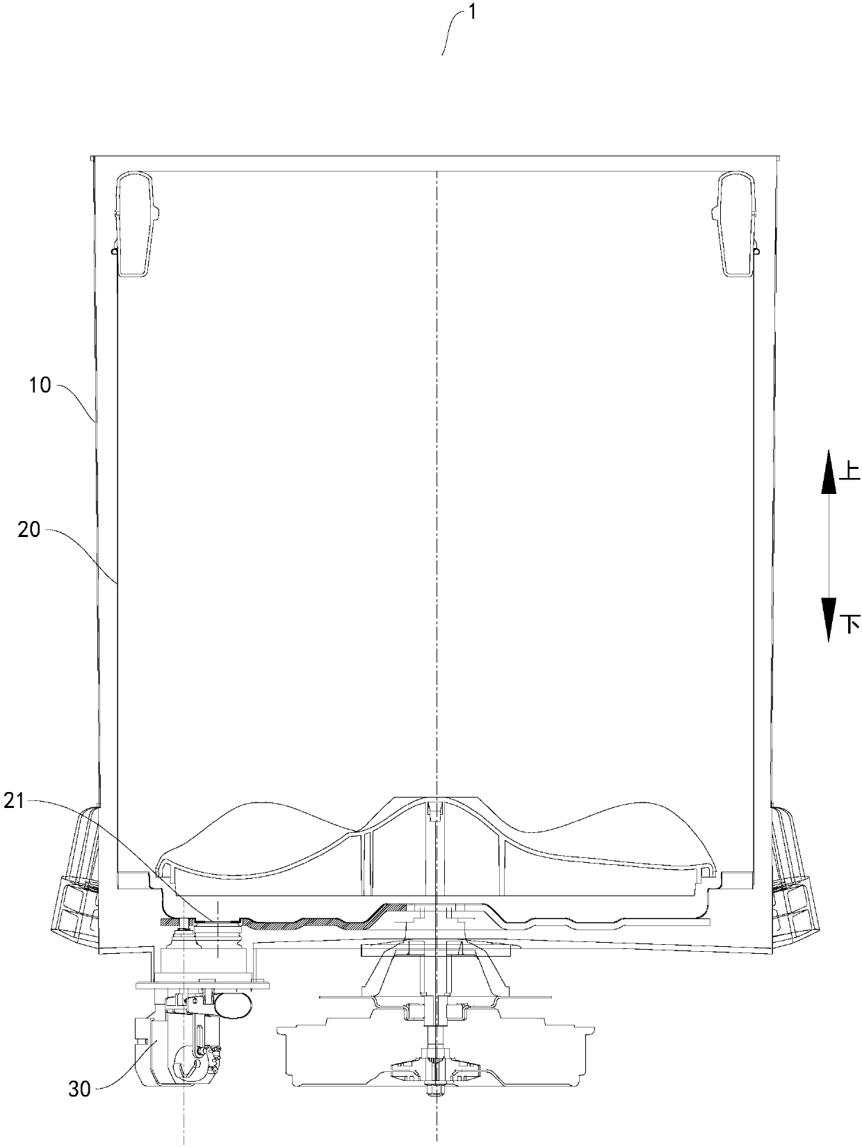
[0004] Wherein, when the dehydration bucket is locked, the drain outlet of the dehydration bucket is closed by the drainage sealing structure, and when the dehydration bucket rotates, the drainage sealing structure opens the drainage outlet of the dehydration bucket, and the water in the dehydration bucket first flows into the water storage bucket from the outlet, and then Then it is discharged from the water tank, but in the process, on the one hand, the drainage speed is slow, and on the other hand, the dander in the dehydration bucket will pollute the water tank.

Method used


Image

  • Washing machine and water discharging mechanism thereof
  • Washing machine and water discharging mechanism thereof
  • Washing machine and water discharging mechanism thereof

Examples


Embodiment Construction

[0042] Embodiments of the present invention are described in detail below, examples of which are shown in the drawings, wherein the same or similar reference numerals designate the same or similar elements or elements having the same or similar functions throughout. The embodiments described below by referring to the figures are exemplary only for explaining the present invention and should not be construed as limiting the present invention.

[0043] In describing the present invention, it is to be understood that the terms "upper", "lower", "vertical", "horizontal", "top", "bottom", "inner", "outer" etc. indicate an orientation or position The relationship is based on the orientation or positional relationship shown in the drawings, and is only for the convenience of describing the present invention and simplifying the description, rather than indicating or implying that the referred device or element must have a specific orientation, be constructed and operated in a specific ...


PUM


Abstract

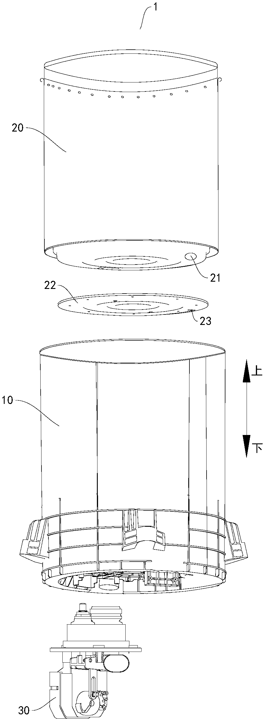
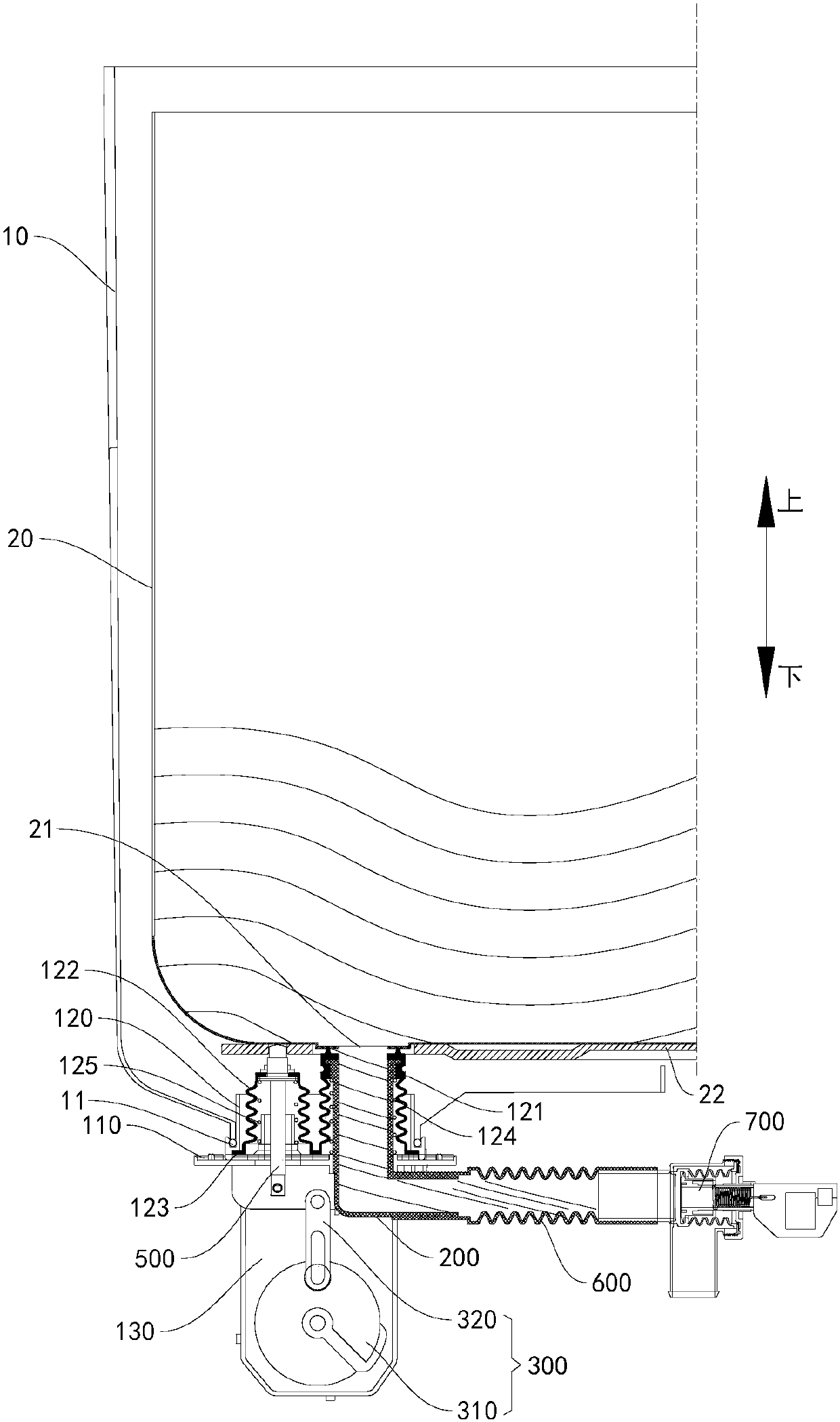
The invention discloses a washing machine and a water discharging mechanism thereof. The water discharging mechanism used for the washing machine comprises a shell body, a water discharging pipe, a transmission assembly and a drive device. The shell body is suitable for installing on a water cylinder of the washing machine; the water discharging pipe is movably installed on the shell body betweena extending position and a retracting position, when the water discharging pipe is located at the extending position, the water discharging pipe is suitable for abutting against a dewatering cylinderof the washing machine and being communicated with a water discharging outlet of the dewatering cylinder; when the water discharging pipe is located at the retracting position, the water discharging pipe is suitable for separating from the dewatering cylinder. The transmission assembly is installed on the shell body and in transmission connection with the water discharging pipe; the drive device is installed on the shell body, and the drive device is in transmission connection with the transmission assembly and drives the water discharging pipe to move between the extending position and the retracting position through the transmission assembly. According to the embodiment of the invention, the water discharging mechanism of the washing machine has the advantages of being fast in water discharging speed and capable of reducing pollution to the water cylinder.

Description

technical field [0001] The invention relates to the technical field of electric appliance manufacturing, in particular to a drainage mechanism for a washing machine and a washing machine with the drainage mechanism for a washing machine. Background technique [0002] Such as a pulsator-type washing machine, there are multiple dehydration holes on the surrounding wall of the dehydration bucket, and the dehydration bucket and the water tank are connected. The dehydration bucket is a clothes storage area for washing clothes. This part of the water does not participate in washing, and the water that really participates in washing is the part in the dehydration bucket, which causes a huge waste of water resources. In addition, too much water between the dehydration bucket and the water tank will also reduce the concentration of detergent and affect washing. Effect. In addition, during the washing process, the dehydration bucket is prone to counter-rotation, resulting in failure ...

Claims


Application Information

Patent Timeline
Patent Type & Authority Applications(China)
IPC IPC(8): D06F23/04D06F39/08D06F37/12D06F37/30
CPCD06F23/04D06F37/12D06F37/30D06F39/083
Inventor 李章京周薇杨姚
Owner WUXI LITTLE SWAN ELECTRIC CO LTD
Why Eureka
Try Eureka