A system and method for stabilizing a high-pressure pump

A voltage stabilizing and high pressure technology, which is applied in the direction of fluid pressure actuators, servo meter circuits, mechanical equipment, etc., can solve the problems of hydraulic system shocks, failure to absorb high pressure pump pressure and flow pulsation well, and achieve reliable sealing, Compact structure and high system stability

Active Publication Date: 2020-06-02
BEIJING TIANMA INTELLIGENT CONTROL TECH CO LTD +1
View PDF7 Cites 0 Cited by
  • Summary
  • Abstract
  • Description
  • Claims
  • Application Information

AI Technical Summary

Problems solved by technology

Conversely, if the accumulator inflation pressure is high, it can meet the pressure stabilization requirements of the system under high pressure, but when the system is under low pressure, the accumulator cannot absorb the pressure and flow pulsation of the high pressure pump well, which will affect the entire hydraulic system. The system has a certain impact

Method used


Image

  • A system and method for stabilizing a high-pressure pump
  • A system and method for stabilizing a high-pressure pump
  • A system and method for stabilizing a high-pressure pump

Examples


Embodiment 1

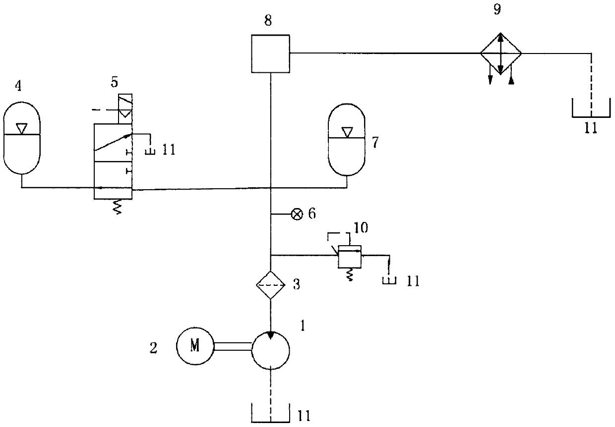
[0041] figure 1 It is the schematic diagram of the voltage stabilizing system tested by the hydraulic pump of the present invention, which mainly includes: 1-the high-pressure pump to be tested; 2-the driving motor; 3-the filter; 4-the low-pressure accumulator; Valve; 6-pressure sensor; 7-high pressure accumulator; 8-pressure regulating valve; 9-cooler; 10-safety valve; 11-liquid tank.

[0042]The driving motor 2 drives the tested high-pressure pump 1 to absorb liquid from the liquid tank 11, and the oil returns to the liquid tank after passing through the filter 3 pressure regulating valve 8 and the cooler 9; Accumulator 7 and a low-pressure accumulator 4, wherein a pilot type electromagnetic reversing valve 5 is connected in series in front of the low-pressure accumulator 4; at the same time, a pressure sensor 6 and a safety valve 10 are connected to the outlet of the high-pressure pump 1 under test.

[0043] Among them, the filter filters the oil, the pressure sensor feeds...

Embodiment 2

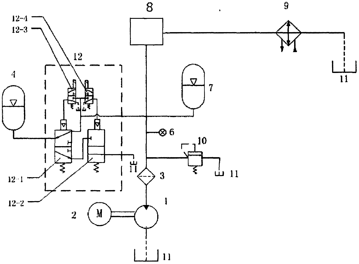
[0047] see image 3 , the other connections of the hydraulic system are the same as those in Embodiment 1. In this embodiment, the electromagnetic reversing valve uses a pilot-operated double-spool electromagnetic reversing valve 12, wherein the inlet of the first valve core 12-1 is connected to the tested high-pressure pump 1 The outlets are connected, the outlets are connected to the low-pressure accumulator 4 and the inlet of the second valve core 12 - 2 , and the outlet of the second valve core 12 - 2 is connected to the liquid tank 11 . Wherein the first spool is responsible for on-off, and the second spool makes the liquid in the low-pressure accumulator return to the liquid tank.

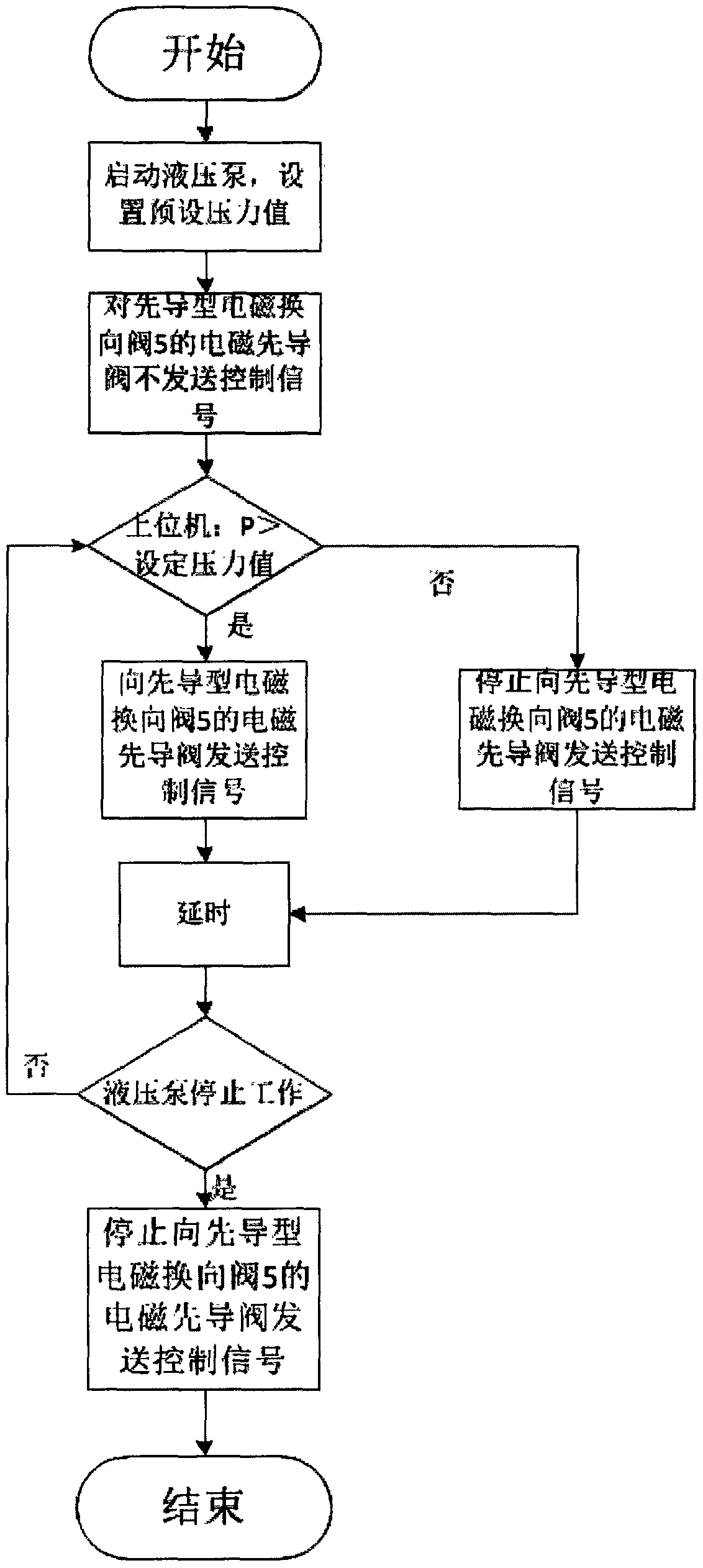
[0048] The voltage stabilization scheme of its hydraulic pump test system is realized by the following voltage stabilization scheme. First, the tested high-pressure pump 1 is started, and the system is in the no-load startup state. The preset pressure value is set in the host computer softwar...

Embodiment 2

[0051] The advantage of adopting the double spool structure in the second embodiment is that if the electromagnetic pilot valve controlling the action of the first spool fails, when the system pressure is greater than the set pressure, the control part will control the action of the first spool and the second spool. The electromagnetic pilot valve sends control signals at the same time. At this time, the first spool does not act due to the failure of the electromagnetic pilot valve that controls the action of the first spool. When the high-pressure oil from the hydraulic pump returns to the liquid tank through this channel, the low-pressure accumulator is protected; if the electromagnetic pilot valve that controls the action of the second spool fails, when the system pressure is greater than the set pressure, the control part sends The electromagnetic pilot valve that controls the actions of the first spool and the second spool sends a control signal at the same time, and the f...


PUM


Abstract

The invention discloses a high-pressure hydraulic pump testing pressure stabilizing system and method. The pressure stabilizing system comprises a tested hydraulic pump, a high-pressure energy accumulator, a low-pressure energy accumulator, an energy accumulator switching device, a pressure sensor and a control part. The high-pressure energy accumulator is connected with a hydraulic pump outlet oil path. The low-pressure energy accumulator is connected with the hydraulic pump outlet oil path through the energy accumulator switching device. After the tested hydraulic pump is started, the pressure sensor monitors the oil path pressure, and when the pressure is smaller than the preset value, oil enters the low-pressure energy accumulator through the energy accumulator switching device, and system pressure stability is maintained through the low-pressure energy accumulator. When the pressure is larger than the preset value, the control part controls the energy accumulator switching deviceto conduct switchover, the oil path and a low-pressure energy accumulator channel are cut off, and system pressure stability is maintained through the high-pressure energy accumulator.

Description

technical field [0001] The invention relates to a hydraulic pump stabilizing system, in particular to a high-pressure hydraulic pump testing stabilizing system and a usage method. Background technique [0002] At present, high-pressure hydraulic pumps generally adopt a plunger structure, so pressure and flow pulsations often occur in the hydraulic system. The pulsation can be reduced by connecting an accumulator at the outlet of the hydraulic pump. However, in the performance test of the high-pressure hydraulic pump, due to the The nominal pressure is very high, and the hydraulic pump factory test must be overloaded, which leads to a very large pressure regulation range of the entire oil system, even reaching 0-50Mpa. At present, a single accumulator is commonly used in the pump test hydraulic system. In the high-pressure test system, if the accumulator inflation pressure is low, although it can meet the pressure stabilization requirements of the system under low pressure co...

Claims


Application Information

Patent Timeline
Patent Type & Authority Patents(China)
IPC IPC(8): F15B1/02
CPCF15B1/02F15B2211/50
Inventor 韦文术刘文超李俊士王伟周如林李然王大龙刘杰王松
Owner BEIJING TIANMA INTELLIGENT CONTROL TECH CO LTD
Why Eureka
Try Eureka