An integrated circuit time parameter testing circuit and method

An integrated circuit, time parameter technology, applied in the direction of electronic circuit testing, measuring electricity, measuring devices, etc., can solve problems such as unsatisfactory signal quality, and achieve the effect of solving time parameter testing requirements and solving complex effects.

Active Publication Date: 2019-12-13
BEIJING HUAFENG TEST & CONTROL TECH CO LTD
View PDF15 Cites 0 Cited by
  • Summary
  • Abstract
  • Description
  • Claims
  • Application Information

AI Technical Summary

Problems solved by technology

[0003] The purpose of the present invention is to propose an integrated circuit time parameter test circuit and method to solve the problem of time parameter test when the test requirements become complicated, or when the signal quality is not ideal due to interference, impedance discontinuity and other factors

Method used


Image

  • An integrated circuit time parameter testing circuit and method
  • An integrated circuit time parameter testing circuit and method
  • An integrated circuit time parameter testing circuit and method

Examples


Embodiment 1

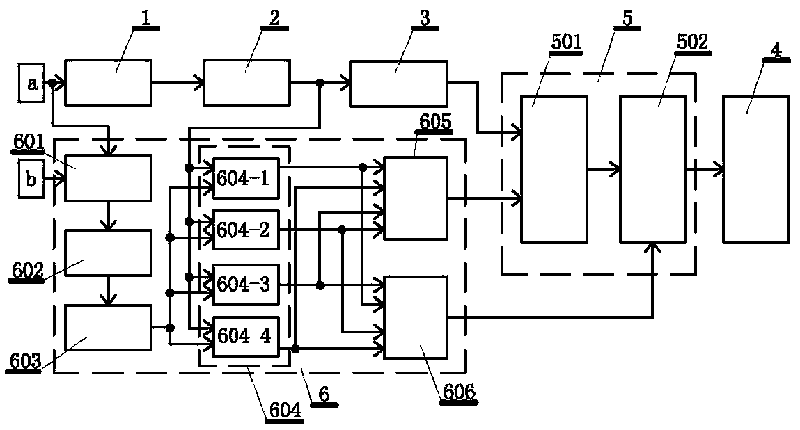
[0031] An integrated circuit time parameter test circuit, such as figure 1 As shown, it includes a tested signal conditioning unit 1, a tested signal trigger unit 2, a first start / stop signal generating unit 3 and a time measuring unit 4, and the tested signal conditioning unit receives the measured signal input waveform a outputted by the integrated circuit After waveform sorting (potential adjustment and filtering), the sorted measured signal is output to the measured signal trigger unit 2, and a comparison circuit (such as a voltage comparator) is set in the measured signal trigger unit 2, and the measured signal is triggered Unit 2 outputs the start / stop signal to the first start / stop signal generation unit 3 after the sorted measured signal is compared with the set start / stop signal trigger level by the comparison circuit, and the first start / stop signal The generating unit 3 generates a trigger pulse from the start / stop signal, and the generated trigger pulse controls th...

Embodiment 2

[0038]This embodiment is an integrated circuit time parameter test method based on an integrated circuit time parameter test circuit in embodiment 1, so the content in embodiment 1 should be regarded as the content of this embodiment, and the integrated circuit time parameter test circuit includes Microprocessor control, the method steps include: inputting signals to the integrated circuit under test, connecting the input waveform of the measured signal output by the integrated circuit to the time measurement unit, synchronously displaying the input waveform of the measured signal and the main frequency pulse waveform of the microprocessor on the On the oscilloscope, use the oscilloscope to visually observe the input waveform of the measured signal output by the integrated circuit, determine the measured parameter object of the measured signal input waveform, and perform time measurement on the determined measured parameter object of the measured signal input waveform. The steps...


PUM


Abstract

The invention discloses a testing circuit and a testing method for time parameters of an integrated circuit. The testing circuit comprises a tested signal conditioning unit, wherein the tested signalconditioning unit is used for finishing an input waveform of a received tested signal outputted by the integrated circuit and then outputting the tested signal to a tested signal trigger unit; in thetested signal trigger unit, the finished tested signal is compared with a set start / stop signal trigger level by a comparison circuit and then the start / stop signal is outputted to a first start / stopsignal generating unit; the first start / stop signal generating unit is used for enabling the start / stop signal to generate trigger pulse for controlling a time measuring unit to measure the time parameters of the tested signal; a start / stop signal control unit is arranged between the first start / stop signal generating unit and the time measuring unit. According to the testing circuit and the testing method disclosed by the invention, the time measuring unit is controlled to start / stop shutoff and opening of a signal gate by setting proper trigger conditions, the test problem of the time parameters when the quality of the tested signal is imperfect can be solved, and test demands of complex time parameters are effectively met.

Description

technical field [0001] The invention belongs to the field of integrated circuit testing, and in particular relates to an integrated circuit time parameter testing circuit and method. Background technique [0002] As integrated circuit designers hope that the designed integrated circuits can meet the increasingly stringent requirements of users in terms of speed and response time, the test of time parameters is becoming more and more common and important. Most semiconductor automatic test equipment has its own time measurement module, which can be used to measure rise / fall time, period / frequency, duty cycle, transmission delay, etc. These time measurement modules receive the signal input to be tested, and after signal conditioning such as amplitude conversion, filtering, and comparator triggers, they generate start and stop signals for time measurement, which are input to the time measurement unit for testing. These time measurement modules can be competent when the test req...

Claims


Application Information

Patent Timeline
Patent Type & Authority Patents(China)
IPC IPC(8): G01R31/28
CPCG01R31/2882
Inventor 刘学涛赵运坤王东海周鹏
Owner BEIJING HUAFENG TEST & CONTROL TECH CO LTD
Why Eureka
Try Eureka