
Testing device and testing method for relay protection device

A relay protection device and detection device technology, applied in the direction of measuring devices, measuring electricity, measuring electrical variables, etc., can solve problems such as low work efficiency, heavy workload, and easy omissions, so as to reduce losses, effectively manage, and timely The effect of rush repair

Active Publication Date: 2018-04-13
HUZHOU ELECTRIC POWER SUPPLY CO OF STATE GRID ZHEJIANG ELECTRIC POWER CO LTD +1
View PDF6 Cites 2 Cited by
  • Summary
  • Abstract
  • Description
  • Claims
  • Application Information

AI Technical Summary

Problems solved by technology

[0004] The invention mainly solves the problems in the prior art that the on-site maintenance personnel face heavy workload, much paper consumption, low work efficiency and easy omissions when performing maintenance on the relay protection device, and provides a relay protection device The detection system and method not only detect the relay protection device itself, but also conduct safety supervision on the working environment of the relay protection device at all times, effectively reducing the work intensity of maintenance personnel to record and sort out maintenance information, and improve the efficiency and accuracy of maintenance , and greatly reduce the amount of paper used to make the remediation work more green and environmentally friendly

Method used


Image

  • Testing device and testing method for relay protection device
  • Testing device and testing method for relay protection device
  • Testing device and testing method for relay protection device

Examples


Embodiment

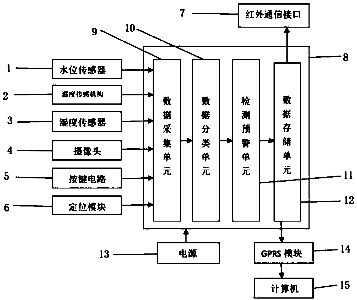
[0041] This embodiment is a detection device of a relay protection device, such as figure 1 As shown, it includes: microprocessor 8, temperature sensing mechanism 2, humidity sensor 3, camera 4, key circuit 5, positioning module 6, computer 15, power supply 13, infrared communication interface 7, GPRS module 14, microprocessor and Power connection

[0042] Microprocessor, including data collection unit 9, data classification unit 10, detection and early warning unit 11, data storage unit 12, data collection unit, data classification unit, detection and early warning unit, data storage unit are connected in sequence, temperature sensor, humidity sensor, camera , The button circuit and the positioning module are respectively connected with the data acquisition unit.

[0043] The present invention collects information related to the maintenance of the relay protection device through the temperature sensing mechanism, humidity sensor, water level sensor, camera, key circuit, and positi...


PUM


Abstract

The invention relates to a testing device and a testing method for a relay protection device. The testing device comprises a microprocessor, a temperature sensing mechanism, a humidity sensor, a camera, a button circuit, a positioning module, a computer, a power supply, an infrared communication interface and a GPRS module. The microprocessor is connected with the power supply. The microprocessormainly comprises a data acquisition unit, a data classifying unit, a testing early-warning unit and a data storage unit. The temperature sensing mechanism, the humidity sensor, the camera, the buttoncircuit and the positioning module are connected with the data acquisition unit. The infrared communication interface is connected with the data storage unit. The testing device and the testing methodmainly settle problems such as high workload and high paper consumption amount of field maintenance personnel in the maintenance process of the relay protection device. The testing device and the testing method for the relay protection device have advantages of effectively reducing working strength of maintenance personnel in recording and sorting information, improving maintenance efficiency andaccuracy, and greatly reducing power consumption amount for realizing higher environment-friendly performance in the sorting operation.

Description

Technical field [0001] The invention relates to the field of maintenance of relay protection devices, and in particular to a detection device and method of a relay protection device. Background technique [0002] At present, due to the gradual expansion of my country's power grid and the continuous development and improvement of the power system, the requirements for on-site debugging of relay protection are getting higher and higher, and the area of ​​relay protection is becoming more and more complicated. On-site debugging of relay protection can quickly reflect the operation of power equipment, and to a certain extent prevent power system failures and reduce losses caused by power failures. However, at present, on-site maintenance personnel are facing problems such as heavy workload and paper problems when renovating the relay protection device, and their work efficiency is low, and they are easy to leak. In order to effectively reduce the work intensity of maintenance person...

Claims


Application Information

Patent Timeline
IPC IPC(8): G01R31/00G01D21/02G08C17/02
CPCG01D21/02G01R31/00G08C17/02
Inventor 童大中丁鸿
Owner HUZHOU ELECTRIC POWER SUPPLY CO OF STATE GRID ZHEJIANG ELECTRIC POWER CO LTD
Learn More