Motor rotor detection assembly and motor

A technology for detecting components and motor rotors, which is applied in the direction of electric components, electrical components, electromechanical devices, etc., can solve problems such as inoperability and reduced motor efficiency, and achieve the effects of preventing inoperability, improving motor efficiency, and improving detection accuracy

Pending Publication Date: 2018-04-13
ZHUHAI GREE REFRIGERATION TECH CENT OF ENERGY SAVING & ENVIRONMENTAL PROTECTION
View PDF0 Cites 2 Cited by
  • Summary
  • Abstract
  • Description
  • Claims
  • Application Information

AI Technical Summary

Problems solved by technology

[0005] Therefore, the technical problem to be solved by the present invention is to overcome the defects of motors in the prior art that reduce the efficiency of the motor due to the poor installation position of the Hall sensor, or even fail to operate, thereby providing a motor rotor detection assembly and a motor

Method used


Image

  • Motor rotor detection assembly and motor
  • Motor rotor detection assembly and motor
  • Motor rotor detection assembly and motor

Examples


Embodiment Construction

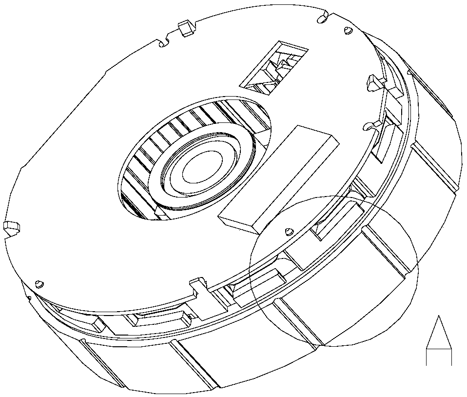
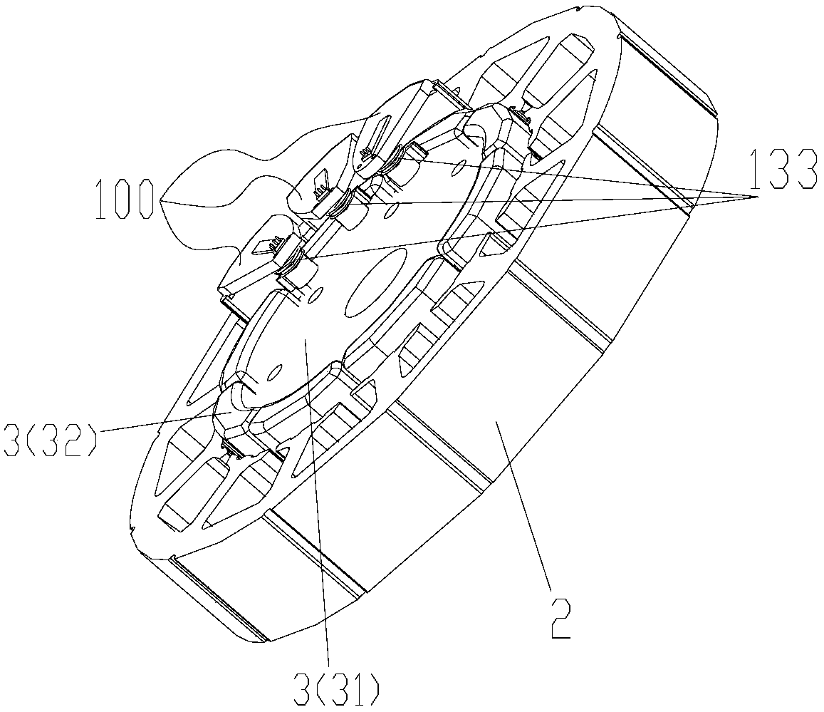
[0057] see Figure 3-5 As shown, the present invention provides a motor rotor detection assembly 100, which includes:

[0058] Mounting bracket 1, one end can be fixedly installed on the motor stator 2, and the other end can extend to the axial side of the motor rotor 3 (including the rotor iron core 31 and the magnetic tile 32) and the position opposite to the motor rotor (preferably The radial inner side of the magnetic tile 32);

[0059] The sensor 4 is arranged on the other end of the mounting bracket 1 to be able to detect the position of the motor rotor 3 .

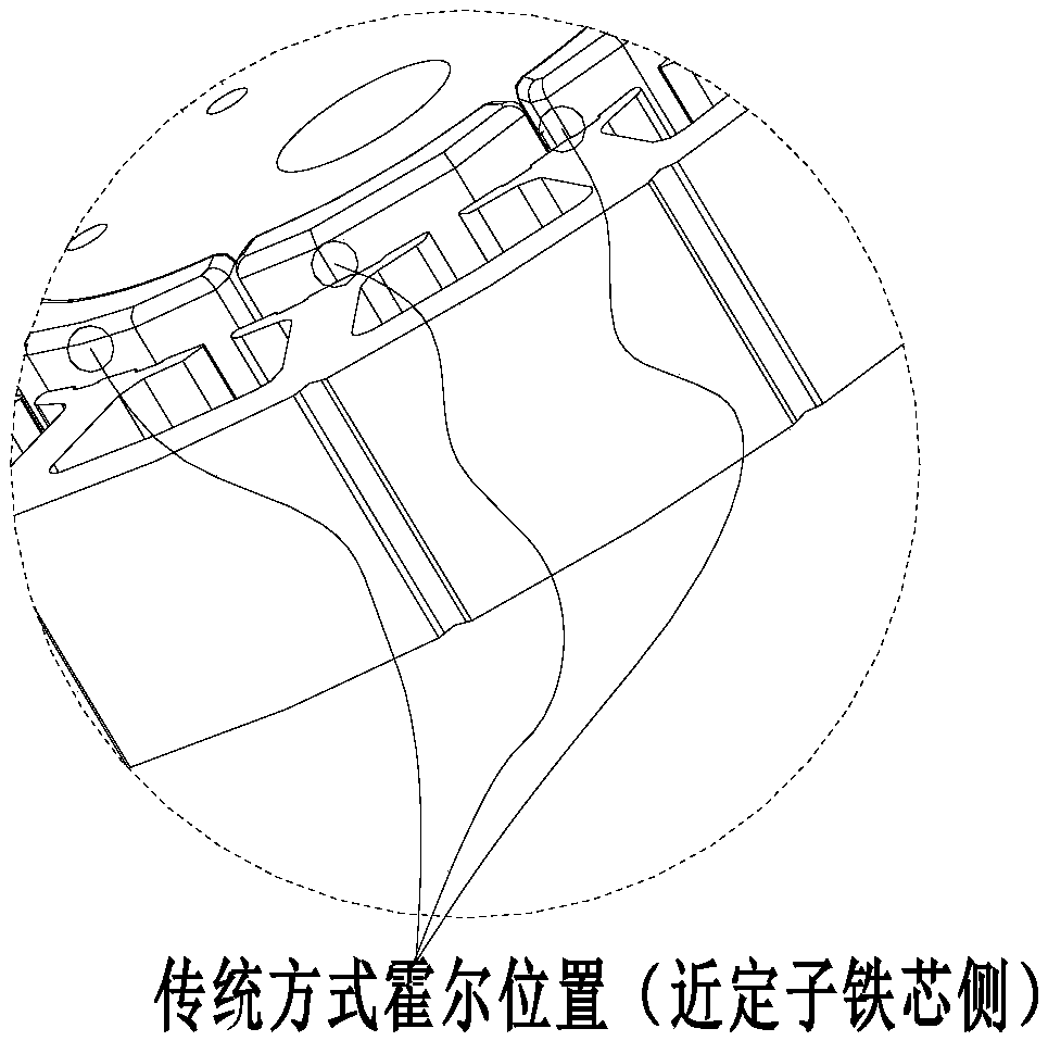
[0060]In the present invention, a mounting bracket is provided, and one end of the mounting bracket can be fixedly installed on the motor stator, and the other end can extend to one axial side of the motor rotor; and the sensor is arranged on the other end of the mounting bracket to It can detect the position of the motor rotor; it can be compared with the scheme in the prior art that the Hall sensor is arranged o...


PUM


Abstract

The invention provides a motor rotor detection assembly and a motor. The motor rotor detection assembly (100) comprises a mounting bracket (1) and a sensor (4), wherein one end of the mounting bracketcan be fixedly mounted on a motor stator (2) while the other end can extend to one axial side of a motor rotor (3) in a position opposite to the motor rotor; and the sensor (4) is arranged at the other end of the mounting bracket (1) and can detect the position of the motor rotor (3). By virtue of the motor rotor detection assembly, the sensor can be mounted to the accurate position, the detection precision is greatly improved, the motor efficiency is improved, the condition that the motor cannot operate can be prevented effectively, and continuous and effective motor operation can be ensured; and detection can be performed by keeping the position of the sensor unchanged, so that influence to the rotor detection precision caused by movement of the sensor can be prevented, thereby effectively improving rotor position detection accuracy.

Description

technical field [0001] The invention belongs to the technical field of motors, and in particular relates to a motor rotor detection component and a motor. Background technique [0002] The existing current DC motors use Hall sensors to detect the rotor position in real time, and feed back the detected rotor position signal to the controller to realize the commutation of the motor, and generate a rotating magnetic field of the synchronous rotor in the stator. Therefore, the relative position of the Hall sensor and the rotor determines the best commutation position of the motor stator, and the best commutation position ensures that the stator current is synchronized with the electromotive force to achieve maximum torque output and optimal efficiency. [0003] However, in this way, the Hall position is installed during the production process. Due to the installation tolerance of the circuit board and the matching tolerance between the circuit board and the stator, the relative ...

Claims


Application Information

Patent Timeline
Patent Type & Authority Applications(China)
IPC IPC(8): H02K11/215
CPCH02K11/215
Inventor 王庆凯孙超王周叶张之元邱东霖孟兆平
Owner ZHUHAI GREE REFRIGERATION TECH CENT OF ENERGY SAVING & ENVIRONMENTAL PROTECTION
Why Eureka
Try Eureka