
Joint frequency phase estimation method based on partial decoupling

A technology of partial solution and frequency offset estimation, applied in multi-frequency code systems, digital transmission systems, electrical components, etc. Feasibility, reduced computational complexity, reduced impact

Inactive Publication Date: 2018-04-13
XIDIAN UNIV
View PDF13 Cites 7 Cited by
  • Summary
  • Abstract
  • Description
  • Claims
  • Application Information

AI Technical Summary

Problems solved by technology

Both of these two algorithms need to use sufficient pilot resources to obtain better estimation performance, and neither considers the impact of frequency offset estimation on phase offset estimation performance
However, in space communication, limited pilot resources can easily lead to inaccurate frequency offset estimation and seriously affect the performance of subsequent phase offset estimation.
Rice F considered in the paper "Carrier-phase and frequency-estimationbounds for transmissions with embedded reference symbols" (IEEE Transactions on Communications, 2006, 54(2): 221-225) that when the length of the burst structure is set to an odd number, artificial In the situation where the sampling zero time at the receiving end is set in the middle of the burst structure, the decoupling characteristics of the Cramereau bound of the joint frequency-phase estimation are found, but the complexity of the phase deviation estimation is high, and in practical applications, artificial It is not feasible to accurately set the sampling zero time position of the receiving end

Method used


Image

  • Joint frequency phase estimation method based on partial decoupling
  • Joint frequency phase estimation method based on partial decoupling
  • Joint frequency phase estimation method based on partial decoupling

Examples


Embodiment Construction

[0031] The embodiments and effects of the present invention will be described in detail below in conjunction with the accompanying drawings.

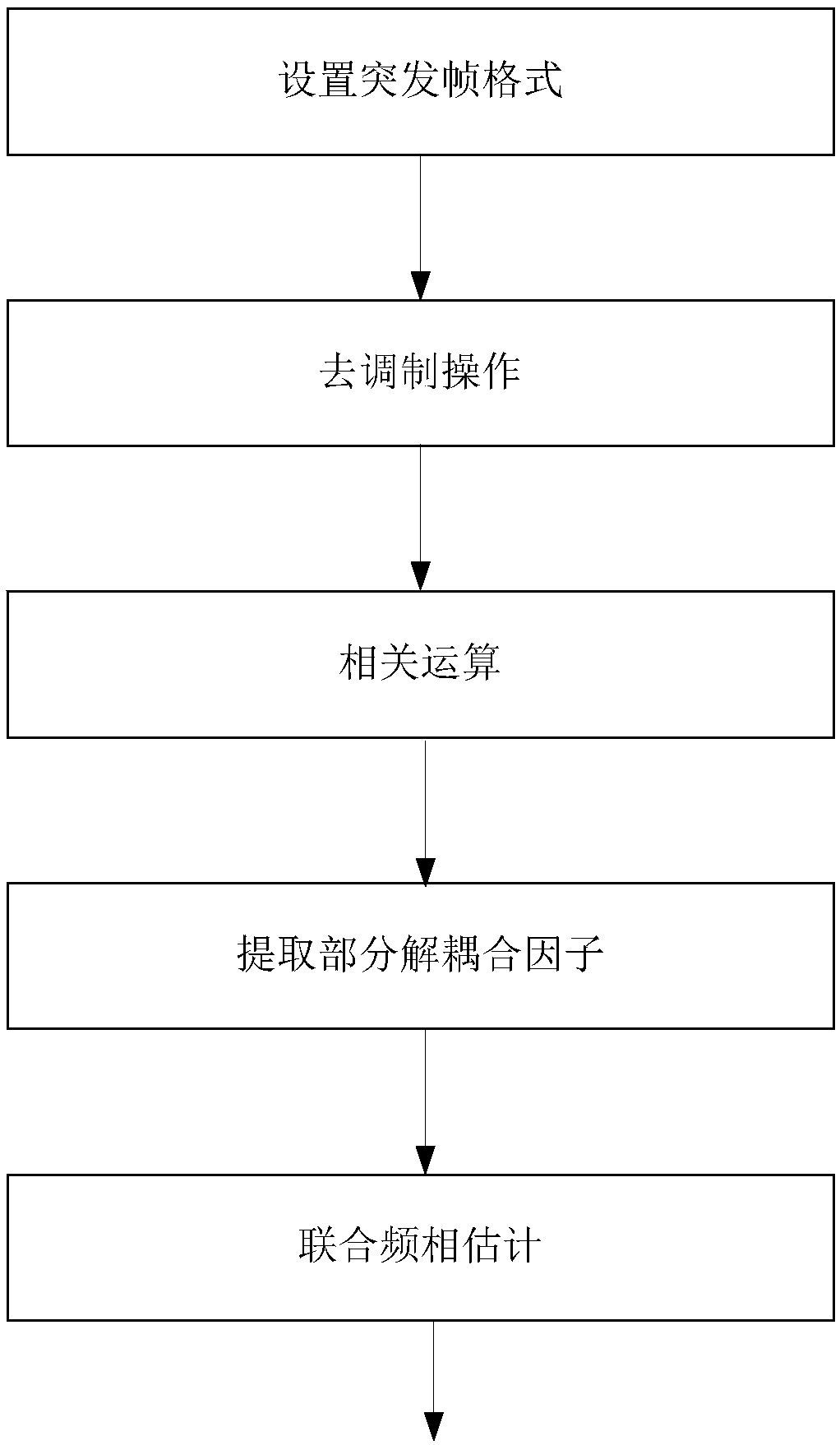
[0032] refer to figure 1 , the implementation steps of the present invention are as follows:

[0033] Step 1, set the burst frame format.

[0034] 1a) Generate a pilot block P of length L 1 and a data block D of length N 1 , and a periodic "data-pilot" distribution pattern P-D with length N';

[0035] 1b) Data block D 1 , pilot block P 1 and the distribution pattern P-D are sequentially multiplexed and connected to get the following figure 2 Burst frame format F shown.

[0036] Step 2, performing a demodulation operation.

[0037] Using the corresponding pilot block P 1 The received signal r P1 (k) Perform conjugate multiplication operation with its modulation signal s(k) to obtain the demodulated signal z(k):

[0038]

[0039] Among them, κ P1 ={N,N+1,...,N+L-1} is the corresponding pilot block P obtained by setting the...


PUM


Abstract

The invention discloses a joint frequency phase estimation method based on partial decoupling. The problem of failed subsequent phase offset estimation caused by large carrier frequency offset of traditional joint frequency phase estimation is solved. The technical scheme comprises the steps that 1 on a receiving end, any pilot signal is demodulated to acquire a demodulated signal; 2 correlation operation is carried out on the demodulated signal and a delayed signal whose sampling time interval is alpha, and the result of the correlation operation is used to acquire a frequency offset estimation value; and 3 the maximum likelihood phase offset estimation is carried out on the conjugate form of the correlation operation result taking alpha as the half of the pilot length and the demodulatedsignal jointly to acquire a phase offset estimation value. According to the invention, the anti-frequency offset ability of phase offset estimation is improved; the complexity of phase offset estimation is reduced; the sampling zero time position of the receiving end is not manually set; the feasibility in practical applications is improved; and the method can be used for space communication including satellite communication, unmanned aerial vehicle communication and spaceflight test control.

Description

technical field [0001] The invention belongs to the technical field of wireless communication, and in particular relates to a joint frequency-phase estimation method, which can be used in space communication including satellite communication, unmanned aerial vehicle communication and aerospace measurement and control. Background technique [0002] In space communication, the transmitting and receiving ends often face two unfavorable factors: large Doppler frequency shift and less pilot resources, which will seriously affect the performance of coherent demodulation. For this reason, it is necessary to introduce carrier synchronization at the receiving end, that is, the traditional joint frequency-phase estimation link. The traditional joint frequency-phase estimation process is a serial processing process, that is, the frequency offset estimation is performed first and then the phase offset estimation is performed. Obviously, the performance of frequency offset estimation wi...

Claims


Application Information

Patent Timeline
Patent Type & Authority Applications(China)
IPC IPC(8): H04L27/00H04L27/26
CPCH04L27/0014H04L27/2657H04L2027/0026H04L2027/0087
Inventor 白宝明倪耀垚余忠洋张强
Owner XIDIAN UNIV
Learn More