Automobile signal lamp LED electronic control module

An electronic control and signal light technology, applied in the field of automobile signal lights, can solve the problems of difficult to meet the lamp body shape design, the optical system light decay can not achieve the expected effect, and it is difficult to achieve standardization, so as to reduce the number of electronic components and reduce the number of components. Cost, effect of avoiding short circuit risk

Inactive Publication Date: 2018-04-13
HASCO VISION TECHNOLOGY CO LTD
View PDF7 Cites 2 Cited by
  • Summary
  • Abstract
  • Description
  • Claims
  • Application Information

AI Technical Summary

Problems solved by technology

Faced with the increasingly thinner and smaller rear lamp design, the system design scheme of this rear fog lamp has become more and more difficult to meet the design of the lamp body, and it is also difficult to achieve standardization, so that a rear fog lamp The electronic control system is suitable for the lamp body structure of the rear lamp of all models
[0005] Commonly used rear fog lamp LED electronic control system design methods are: place the LED light source and LED driver together on the same PCB board, and the LED driver adopts a simple resistive or linear constant current method, because there are only a few resistors or linear constant current. There is only one flow chip, and the circuit of the LED driving part will not take up too much space, so this solution can basically meet the miniaturization design, but due to the efficiency of the LED driving and the influence of the heat generated on the LED, the optical system The light attenuation cannot achieve the expected effect

Method used


Image

  • Automobile signal lamp LED electronic control module
  • Automobile signal lamp LED electronic control module
  • Automobile signal lamp LED electronic control module

Examples


Embodiment Construction

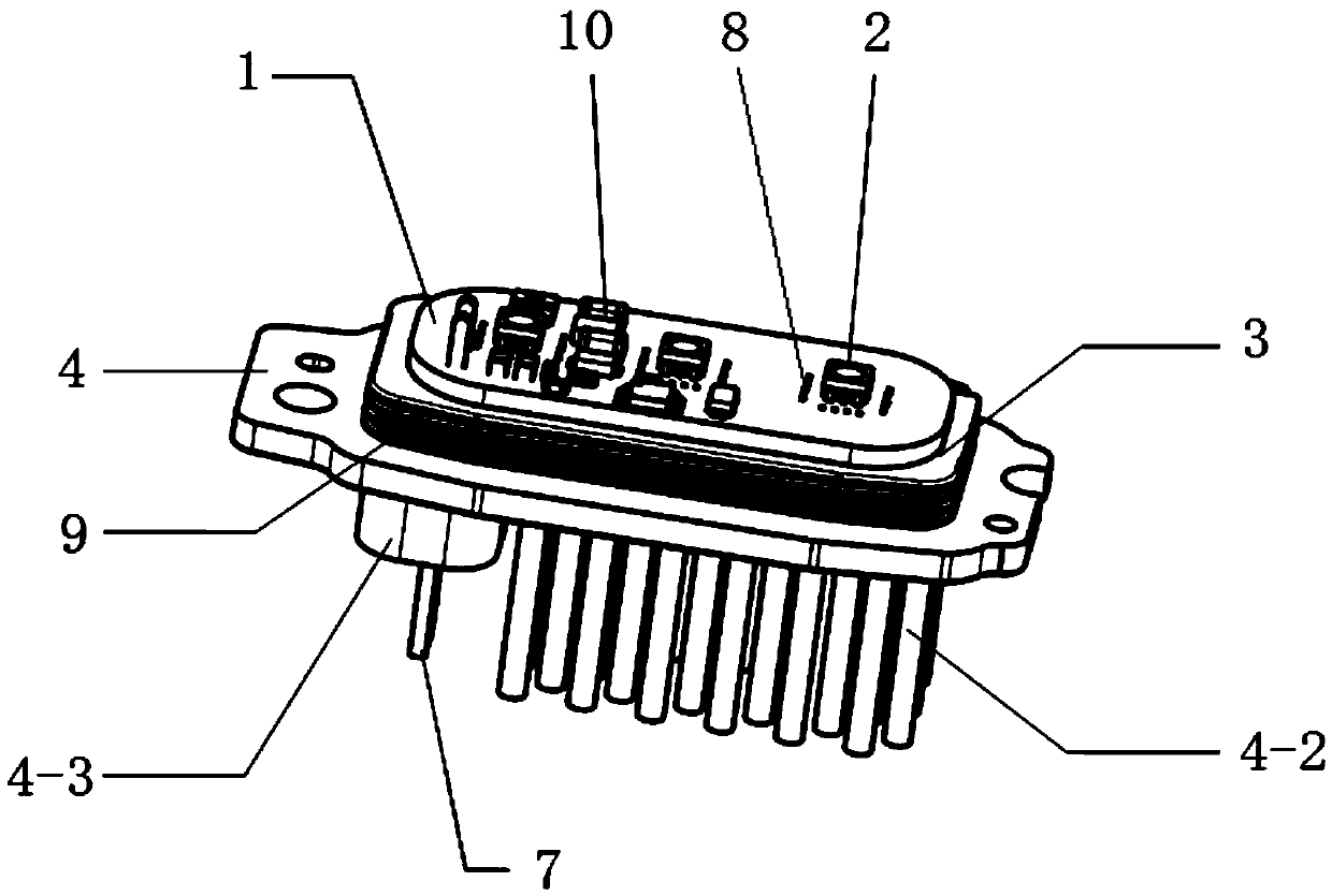
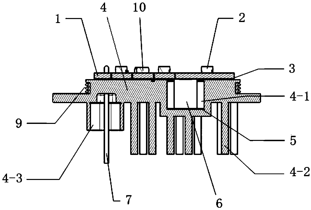
[0028] Such as figure 1 , 2 As shown, the present invention discloses an automotive signal lamp LED electronic control module, which includes an LED string and a drive circuit for the LED string (containing multiple electronic components, figure 1 Only the power device 6 and some other electronic component 10 are shown) and the same circuit board 1 on which the LED string and the driving circuit are arranged. The LED string includes one or more LEDs 2 connected in series. The circuit board is covered and fixed to the top surface of the radiator 4 through the heat dissipation adhesive layer 3, and the radiator is provided with a sink groove 4-1, which opens on the top surface of the radiator. The power device of the drive circuit is installed under the circuit board (or called the reverse side) and is located in the sink, and other electronic components of the drive circuit and the LED are all mounted on the circuit board. Top (or positive). The lower part of the heat sink is a ...


PUM


Abstract

The invention relates to an automobile signal lamp LED electronic control module. The automobile signal lamp LED electronic control module comprises an LED string, a driving circuit of the LED stringand a circuit board on which the LED string and the driving circuit are arranged, wherein the LED string comprises one or multiple LED which are connected in series, the circuit board covers a top surface of a radiator and is further fixedly bonded on the top surface of the radiator through a radiation glue layer, the radiator is provided with a sinker, the sinker opening is arranged at the top surface of the radiator, a power device of the driving circuit is mounted below the circuit board and is arranged in the sinker, other electronic devices of the driving circuit and the LED are mounted on the circuit board, a lower portion of the radiator is provided with a radiation structure and a connection lead or a connector inlet port of a PIN needle, and the driving circuit employs a DCDC typedriving circuit BUCK topological structure. The automobile signal lamp LED electronic control module is advantaged in that miniaturization and standardization requirements are satisfied on the condition that the optical system attenuation requirement is satisfied, and one LED lamp module is made to be suitable for all signal lamp body structures.

Description

Technical field [0001] The invention relates to an LED electronic control system, which is mainly suitable for automobile signal lamps using LED light sources. Background technique [0002] LED has significant advantages such as fast response speed, low power consumption, energy saving, and long life. Due to the fast response speed of LED, it is especially suitable for the application of front and rear lamps of automobiles. With the improvement of semiconductor materials and packaging technology, the luminous flux and light output efficiency of LED light sources have gradually increased, and LED light sources have been widely used in the field of automotive lighting. LED drive technology has gradually developed with the development of LED application technology. [0003] LED is used as the source of automobile rear fog light. Due to the requirements of the upper and lower limits of the luminous flux of the optical system in laws and regulations, high requirements are put forward ...

Claims


Application Information

Patent Timeline
Patent Type & Authority Applications(China)
IPC IPC(8): H05B33/08F21V23/00F21V29/508F21Y115/10H05B44/00
CPCF21V23/003F21V29/508F21Y2115/10H05B45/37
Inventor 李佳颖
Owner HASCO VISION TECHNOLOGY CO LTD
Why Eureka
Try Eureka