Automatic mounting equipment for screw sleeve and clamping ring

An automatic installation and snap ring technology, applied in metal processing equipment, metal processing, manufacturing tools, etc., can solve the problems of consumption, large man-hours and labor costs, and achieve the effect of saving manpower and man-hours, high precision and good uniformity

Pending Publication Date: 2018-04-17
FUJIAN MICABLE ELECTRONIC TECH GRP CO LTD
View PDF7 Cites 1 Cited by
  • Summary
  • Abstract
  • Description
  • Claims
  • Application Information

AI Technical Summary

Problems solved by technology

[0004] The technical problem to be solved by the present invention is to provide an automatic installation device for screw sleeves and snap rings, which can solve the problem of consuming a lot of man-hours and labor costs in the traditional installation method of manual cooperation with a hand press

Method used


Image

  • Automatic mounting equipment for screw sleeve and clamping ring
  • Automatic mounting equipment for screw sleeve and clamping ring
  • Automatic mounting equipment for screw sleeve and clamping ring

Examples


Embodiment 1

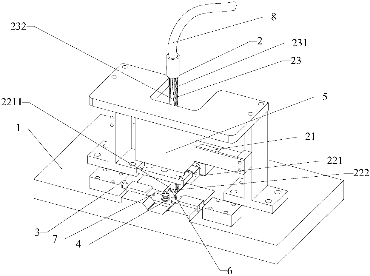
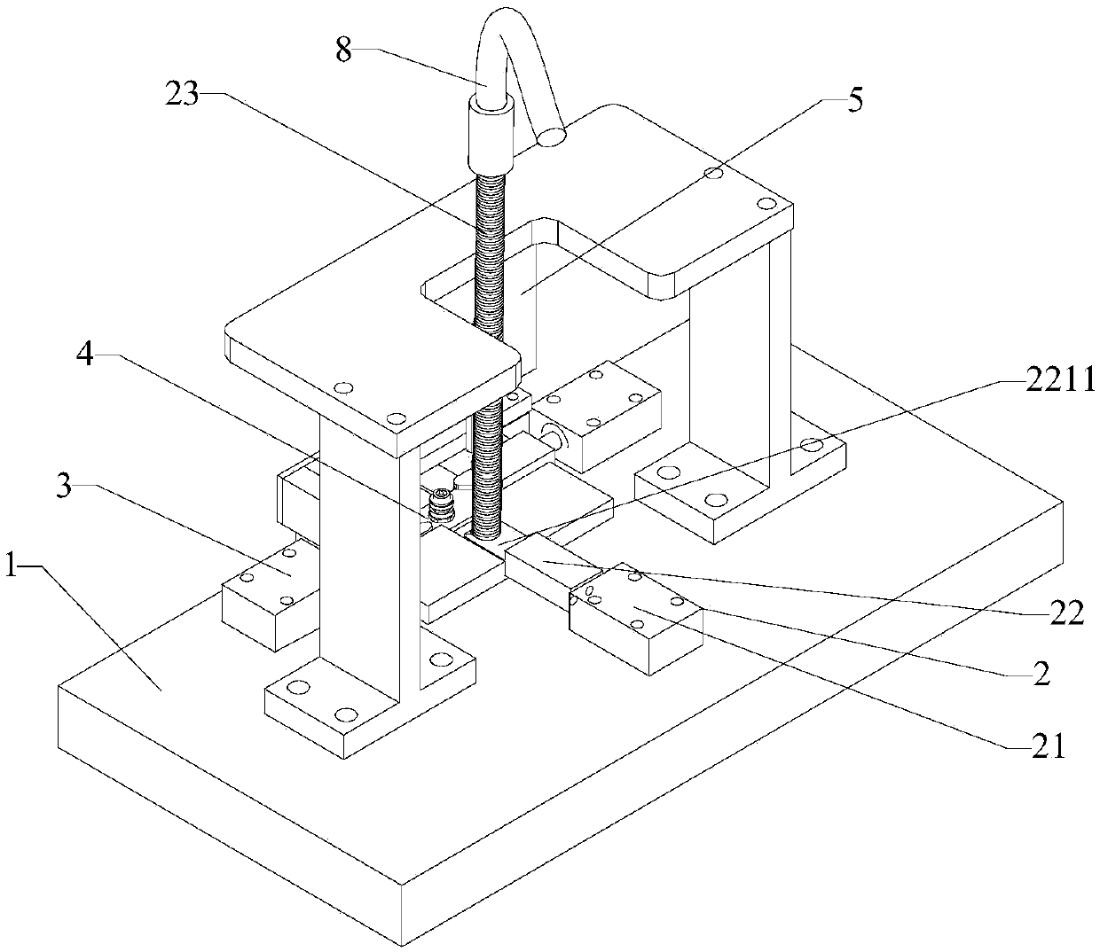
[0041] A screw sleeve and snap ring automatic installation equipment, including a feeding device 2 installed on a base 1, a clasp clamp cylinder 3, a connector mounting seat 4 and a screw sleeve pressing cylinder 5; the feeding device 2 includes a feeding cylinder 21 and the feeder 22 that is connected to the piston end of the feeding cylinder 21; the feeder 22 includes a feeder body 221 and a material holding platform 222, and the feeder body 221 is connected with a material holding platform 222 by a spring 223; the feeding cylinder 21 A connector mounting seat 4 is provided on the moving direction of the connector mounting seat 4, and snap ring clip cylinders 3 which are mirror images of each other are respectively provided on both sides of the connector mounting seat 4; The feeding device 2 also includes a snap ring guide rail 23; the snap ring guide rail 23 includes a cylindrical guide rail body 231 and a limiting flange 232 arranged on the guide rail body 231; the limiting...


PUM


Abstract

The invention relates to automatic mounting equipment for a screw sleeve and a clamping ring. The automatic mounting equipment comprises a feeding device, clamping ring air-entraining cylinders, a connector mounting seat and a screw sleeve press-in air cylinder which are arranged on a base, wherein the feeding device comprises a feeding air cylinder and a feeder connected to a piston end of the feeding air cylinder; the feeder comprises a feeder body and a containing platform, and the feeder body is connected with the containing platform through a spring; the connector mounting seat is arranged in the moving direction of the feeding air cylinder, and the clamping ring air-entraining cylinders which are mirror images of each other are respectively mounted on two sides of the connector mounting seat; and the screw sleeve press-in air cylinder is arranged above the connector mounting seat. By mounting the feeding device, the clamping ring air-entraining cylinders, the connecting mountingseat and the screw sleeve press-in air cylinder on the base, the connection between the clamping ring and the connector and the connection between the screw sleeve and a connector are automatically finished under the control of the controller.

Description

technical field [0001] The invention relates to the technical field of radio frequency connector assembly, in particular to an automatic installation device for a screw sleeve and a snap ring. Background technique [0002] The connection methods of RF connectors (hereinafter referred to as connectors) are mainly divided into snap-in connections, blind insertion, threaded connections, etc. Among them, threaded connections are used in most connectors because of their good reliability and high connection strength. For example, connectors of SMA, N, TNC and other types are threaded. Its structure is as figure 1 , The clasp ring is made of elastic metal material in the shape of a ring, with a cutout for easy installation, and a clasp groove with the same size as the clasp ring is processed on the screw sleeve and the connector body. [0003] The traditional installation method is to manually insert the snap ring into the slot of the connector body, and then clamp the snap ring ...

Claims


Application Information

Patent Timeline
Patent Type & Authority Applications(China)
IPC IPC(8): B23P19/027
CPCB23P19/001B23P19/027
Inventor 曾金荣
Owner FUJIAN MICABLE ELECTRONIC TECH GRP CO LTD
Why Eureka
Try Eureka