
Anti-drone catching device with retrieving function

A capture device and anti-drone technology, applied in the field of aircraft, can solve the problems of poor flexibility, high technical content and cost, low capture rate, etc., and achieve the effect of improving utilization rate, low escape possibility and high capture rate

Active Publication Date: 2018-04-17
天罡(宁波)智能信息科技有限公司
View PDF3 Cites 5 Cited by
  • Summary
  • Abstract
  • Description
  • Claims
  • Application Information

AI Technical Summary

Problems solved by technology

The interference blocking type is to interfere with all the signals of the target UAV by emitting specific electromagnetic wave signals, so that the signal of the UAV is cut off, and the UAV is triggered to return. The countermeasures of this type of method are poor; The laser cannon directly shoots down the UAV. This kind of method has strong countermeasures, but the UAV shot down is easy to cause damage to the ground personnel; the monitoring and control category mainly uses hacking technology to invade the UAV’s operating system, hijack the radio control, and put Captured by UAVs, the technical content and technical cost of such methods are high, and it is difficult to popularize
Nowadays, a kind of capture device for intercepting drones is gradually emerging. The capture device captures the target drone by launching net bombs or using the drone to carry the interception frame. After the net bombs are launched, they can only rely on inertial flight and cannot be adjusted. From the flight angle, the target UAV is easy to escape, the capture rate is low, and there will be problems of falling, hurting people and being unable to recycle. However, the target UAV is intercepted by the UAV carrying the interception frame. frame, its speed is difficult to surpass the target drone, and the flexibility of movement is poor, the capture rate is low, and the practicability is poor

Method used


Image

  • Anti-drone catching device with retrieving function
  • Anti-drone catching device with retrieving function
  • Anti-drone catching device with retrieving function

Examples


Embodiment Construction

[0030] Embodiments of the present invention are described in detail below, examples of which are shown in the drawings, wherein the same or similar reference numerals denote the same or similar elements or elements having the same or similar functions throughout. The embodiments described below by referring to the figures are exemplary only for explaining the present invention and should not be construed as limiting the present invention.

[0031] In describing the present invention, it is to be understood that the terms "length", "upper", "lower", "front", "rear", "vertical", "horizontal", "top", "bottom", The orientation or positional relationship indicated by "inner", "outer", etc. is based on the orientation or positional relationship shown in the drawings, and is only for the convenience of describing the present invention and simplifying the description, rather than indicating or implying that the referred device or element must have Certain orientations, constructed and...


PUM


Abstract

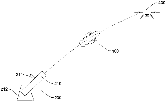
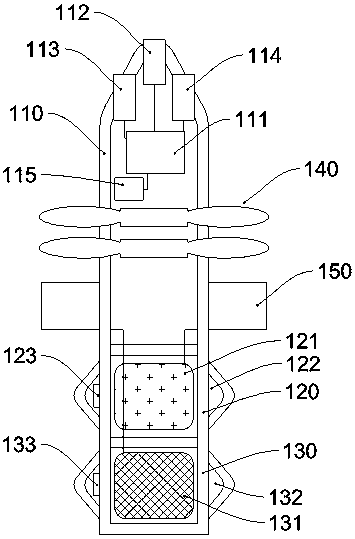
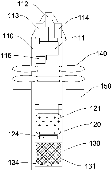
The invention provides an anti-drone catching device with a retrieving function. The anti-drone catching device comprises a head, a tail, small wings, a propeller structure and a smoke shell / signal shell and is characterized in that a catching control system is arranged inside the head and comprises an information collecting module, a control unit and a propeller motor; the information collectingmodule comprises an image collecting module, a laser radar scanning module and a close-range electromagnetic wave detecting module which are connected with the control unit; the propeller motor is connected with the propeller structure; the tail is arranged at the rear of the head and provided with a catching net inside; the small wings are arranged at the head and connected with the control unit;the smoke shell / signal shell is triggered when the catching device falls or after the catching device falls. The anti-drone catching device has the advantages that the device is high in catching rateand recyclable, the escape possibility of a target drone is low, and the utilization rate of the device is increased.

Description

technical field [0001] The invention relates to the field of aircraft, in particular to an anti-drone capture device. Background technique [0002] As more and more drones appear in people's lives, some drones that do not follow the rules often cause troubles to others and even affect public safety. In order to prevent the illegal misuse of drones, a new thing has emerged: anti-drone systems. [0003] The existing anti-drone means mainly include interference and blocking, direct destruction and monitoring and control. The interference blocking type is to interfere with all the signals of the target UAV by emitting specific electromagnetic wave signals, so that the signal of the UAV is cut off, and the UAV is triggered to return. The countermeasures of this type of method are poor; The laser cannon directly shoots down the UAV. This kind of method has strong countermeasures, but the UAV shot down is easy to cause damage to the ground personnel; the monitoring and control ca...

Claims


Application Information

Patent Timeline
Patent Type & Authority Applications(China)
IPC IPC(8): B64C27/10B64C39/02B64D47/00B64D47/02F41H11/04
CPCF41H11/04B64C27/10B64C39/02B64D47/00B64D47/02B64U70/83B64U10/10
Inventor 王娅
Owner 天罡(宁波)智能信息科技有限公司
Learn More