Reciprocating type coring method and device for rock stratum sampling

A coring device and reciprocating technology, applied in the direction of extracting undisturbed cores, earthwork drilling, etc., can solve the problems of reduced coring accuracy, low coring efficiency, and reduced coring quality, so as to improve the quality of coring and improve Effect of improving coring efficiency and coring accuracy

Pending Publication Date: 2018-04-17
HENAN POLYTECHNIC UNIV
View PDF9 Cites 3 Cited by
  • Summary
  • Abstract
  • Description
  • Claims
  • Application Information

AI Technical Summary

Problems solved by technology

The problems in the above method are: the weight of the hollow drill pipe is relatively heavy, the whole process of coring needs to withdraw the pipe many times, the work intensity is extremely high, and due to the frictional resistance between the drill pipe and the borehole, it is difficult to withdraw and enter the pipe. Large and slow speed, resulting in extremely low coring efficiency; due to repeated retracting and advancing rods, it is easy to cause the drilling path to deviate from the predetermined path, resulting in a decrease in coring accuracy; Pollution and damage of layer core samples, destroying its original rock structure, physical, mechanical properties and other indicators, resulting in lower core quality

Method used


Image

  • Reciprocating type coring method and device for rock stratum sampling

Examples


Embodiment 1

[0017] A reciprocating coring method for rock formation sampling, specifically comprising the following steps:

[0018] 1) Drill the hollow drill pipe with the coring chamber fixed at the front end according to the predetermined drilling path. When the drilling depth reaches the coring length, stop drilling and the core enters the coring chamber;

[0019] 2) The hollow drill pipe is fixed, and the coring chamber is taken out along the inner hole of the hollow drill pipe, and then the core is taken out of the core chamber;

[0020] 3) Push the coring chamber into the front end of the hollow drill pipe along the inner hole of the hollow drill pipe and fix it, and then drill and coring according to the predetermined drilling path again;

[0021] 4) Repeat step 1) to step 3) until the total drilling depth reaches the predetermined depth.

Embodiment 2

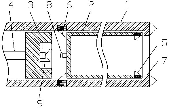
[0023] like figure 1 As shown, a reciprocating coring device for rock formation sampling includes a hollow drill rod 1, a coring bin 2 and a coring rod 4; the coring bin 2 is a cylinder with an open end, and the outer diameter of the cylinder is the same as the hollow The inner diameter of the drill pipe 1 matches; the front end of the inner wall of the hollow drill pipe 1 is provided with a front limit 7 for fixing the coring chamber 2 and a rear limit 6 for the coring chamber, and a front limit 7 for the coring chamber. In order to fix the limit, the limit 6 behind the coring chamber is a one-way limit set along the rear; the coring rod 4 is a hard drill rod, and the front end of the coring rod 4 is provided with a detachable connector 3, The connecting head 3 is used to drive the rear limiter 6 of the coring chamber and is connected with the coring chamber 2 .

[0024] The front end of the inner side wall of the coring chamber 2 is provided with a core limiter 5, which is ...


PUM


Abstract

The invention relates to a reciprocating type coring method for rock stratum sampling. The method comprises the following steps: (1) carrying out drilling by a hollow drill pipe with front end provided with a coring cabin according to a predetermined drilling path, and when the drilling depth reaches the coring length, stopping drilling, and enabling the rock core to enter the coring cabin; (2) when the hollow drill pipe is immobilized, taking out the coring cabin along an inner hole of the hollow drill pipe, and then taking out the rock core from the coring cabin; (3) pushing the coring cabininto the front end of the hollow drill pipe along the inner hole of the hollow drill pipe to be fixed, and then carrying out drilling and coring according to the predetermined drilling path; and (4)repeating the steps (1) to (3) till the total drilling depth reaches a predetermined depth. According to the method and the device, the coring efficiency of the rock stratum can be improved greatly, the work strength is reduced and the coring precision and quality are improved.

Description

technical field [0001] The invention specifically relates to a reciprocating coring method and device for rock formation sampling, and belongs to the technical field of geological drilling. Background technique [0002] During geological engineering operations such as mining, geological exploration is required to obtain indicators such as rock structure, physical, and mechanical properties. Coring the rock formation is the most direct means of exploration. The specific method is to drill down from the surface with a hollow drill pipe to form a cylindrical borehole in the rock formation, and obtain cores, ore samples, and soil samples from different depths in the borehole. Analyze and study samples to identify and classify rock formations. Because the coring depth is relatively large, generally up to hundreds of meters, the traditional coring method is to completely withdraw the hollow drill pipe when a single drilling reaches a certain depth, and then remove the drill pipe ...

Claims


Application Information

Patent Timeline
Patent Type & Authority Applications(China)
IPC IPC(8): E21B25/10
CPCE21B25/10
Inventor 李辉魏建平程磊
Owner HENAN POLYTECHNIC UNIV
Why Eureka
Try Eureka