A laser portable mwd angle difference ruler and its application method

A portable, angular difference technology, which is applied in earthwork drilling, optical devices, measurement, etc., can solve the problems of low accuracy of angular difference measurement, inefficient construction, large trajectory deviation, etc., and achieve the effect of improving the accuracy of angular difference

Active Publication Date: 2021-03-19
BC P INC CHINA NAT PETROLEUM CORP +1
View PDF7 Cites 0 Cited by
  • Summary
  • Abstract
  • Description
  • Claims
  • Application Information

AI Technical Summary

Problems solved by technology

[0003] In order to solve the problems of low angle difference measurement accuracy, large deviation, many errors, calculation errors, large track deviation, and low-efficiency construction in the existing method of measuring angle difference, the present invention provides a laser portable MWD angle difference ruler and its use method. It is convenient for technicians to read the angle directly, reducing the operation errors of technicians, and improving the accuracy of measuring angles at the same time

Method used


Image

  • A laser portable mwd angle difference ruler and its application method
  • A laser portable mwd angle difference ruler and its application method
  • A laser portable mwd angle difference ruler and its application method

Examples


Embodiment 1

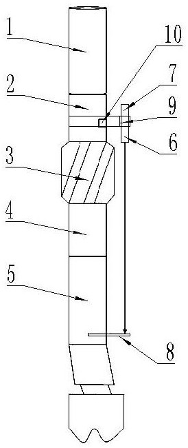
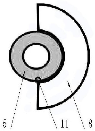
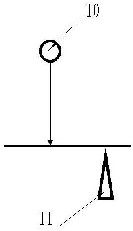
[0027] Such as figure 1 with figure 2 As shown, a laser portable MWD angular difference ruler includes non-magnetic drill collars 1, MWD directional joints 2, centralizers 3, short drill collars 4 and screw rods 5 connected in sequence, and on the side wall of the MWD directional joint 2 A laser pointer 6 is installed, and the light source of the laser pointer 6 is set downwards. A screw high-side marking groove 11 is provided at the screw bending point on the side wall of the lower half of the screw rod 5, and the screw high-side marking groove 11 is abutted with an angular difference by a ruler 8 The 0° scale on the panel of the angular difference is close to the high-side mark groove, and the panel of the angular difference is placed horizontally, and the beam emitted by the laser pointer 6 forms a light spot on the panel of the angular difference.

[0028] When in use, the laser pointer 6 is installed on the side wall of the MWD directional joint 2, so that the light bea...

Embodiment 2

[0031] Such as figure 1 As shown, a laser pointer fixing card 7 is clamped on the side wall of the MWD directional joint 2, and a ring 9 is opened on the laser pointer fixing card 7, and the laser pointer 6 is clamped in the ring 9.

[0032] A positioning bolt 10 that can adjust the position of the laser pointer fixing card 7 is provided at the middle position in the vertical direction of the MWD directional joint 2 , and the positioning bolt 10 is flush with the side wall of the MWD directional joint 2 .

[0033] The laser pointer 6 has the same diameter as the positioning bolt 10 .

[0034] In the process of installing the laser pointer 6 on the side wall of the MWD orientation joint 2, the laser pointer 6 is clamped in the ring 9 of the laser pointer fixing card 7, and the laser pointer fixing card 7 is stuck on the MWD orientation through the buckle. Connector 2. The position of the laser pointer fixing card 7 can be better fixed by the positioning bolt 10. The positioni...

Embodiment 3

[0036] Such as figure 2 As shown, the angular difference ruler 8 includes a front side and a back side, and both the front side and the back side are marked with 0°~180° marks.

[0037] When set bolt 10 is positioned at screw rod high side marking groove 11 left side, angle difference is leaned on ruler 8 panel face up, and when set bolt 10 is positioned at screw rod high side mark groove 11 right side, angle difference leans against ruler 8 panel reverse side upwards.

[0038] Regardless of whether the positioning bolt 10 on the MWD directional joint 2 is located on the left or right side of the marking groove 11 on the high side of the screw rod, the angular difference measurement can be performed conveniently and quickly by using the angular difference ruler 8, which is convenient for technicians to operate.


PUM


Abstract

Provided is a laser portable MWD angle-different guiding rule. The laser portable MWD angle-different guiding rule comprises a non-magnetic drill collar, an MWD directional sub, a centering guide, a short drill collar and a threaded rod. The side wall of the MWD directional sub is equipped with a laser pen. A light source of the laser pen faces downward. The bent-point part of the threaded rod onthe side wall of the lower half part of the threaded rod is provided with a threaded-rod high-side marking groove. The threaded-rod high-side marking groove is in pressing connection with an angular-difference guiding rule. A 0-degree scale of a panel of the angular-difference guiding rule clings to the high-side marking groove. Additionally, the panel of the angular-difference guiding rule is horizontally placed. Light beams generated by the laser pen form light spots on the panel of the angular-difference guiding rule. With the laser portable MWD angle-different guiding rule and an application method thereof, technical staff can conveniently direct read angular-difference degrees while increasing angular-difference precision. Therefore, impact of weather, tape measurement precision, calculation methods, personnel and other factors to existing angular-difference measurement is avoided. The problems of angular differences such as low precision, great deviation and human error are avoided.

Description

technical field [0001] The invention relates to the technical field of drilling tools, in particular to a laser portable MWD angle difference gauge and a method for using it. Background technique [0002] At present, the measurement of MWD angle difference in the drilling process of oil and natural gas directional wells and horizontal wells is to calculate the conversion angle by visual inspection, positioning bolts hanging the weight line, and measuring the circumference of the power drilling tool. This method is easily affected by the weather and the measurement accuracy of the tape Influenced by factors such as the calculation method and the personnel themselves, problems such as low angle difference accuracy, large deviation, many errors, and calculation errors are caused. The directional construction process is likely to cause problems such as large trajectory deviation and inefficient construction. Contents of the invention [0003] In order to solve the problems of ...

Claims


Application Information

Patent Timeline
Patent Type & Authority Patents(China)
IPC IPC(8): E21B47/02G01B11/26
CPCE21B47/02G01B11/26
Inventor 史配铭石崇东王万庆赵保平曲小文王玉鹏党小军朱飞虎李强刘晓燕
Owner BC P INC CHINA NAT PETROLEUM CORP
Why Eureka
Try Eureka