Supercharge Your Innovation With Domain-Expert AI Agents!

Automobile brake device and method

A braking device and automobile technology, applied in the direction of braking transmission, brakes, brake types, etc., can solve the problems of slow braking response, failure of the braking system to achieve energy recovery, and the failure of the braking system to achieve active braking. Achieve the effects of coercive action, high practical value, and accelerated braking speed

Active Publication Date: 2018-04-17
山东丰奥工程机械制造有限公司
View PDF7 Cites 0 Cited by
  • Summary
  • Abstract
  • Description
  • Claims
  • Application Information

AI Technical Summary

Problems solved by technology

[0003] The purpose of the present invention is to solve the problems that the braking system in the prior art cannot realize active braking and slow braking response, and provide a braking device for automobiles that can realize active braking and fast braking and has high safety performance and method
[0004] Another object of the present invention is to solve the problem that the braking system in the prior art cannot realize energy recovery, and to provide an automobile braking device and method that can recover braking energy during braking and save energy

Method used


Image

  • Automobile brake device and method
  • Automobile brake device and method
  • Automobile brake device and method

Examples


Embodiment 1

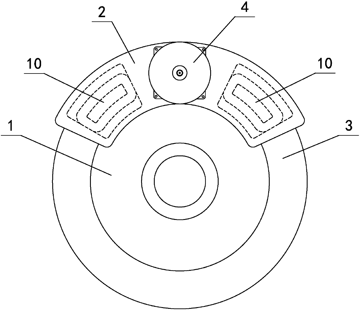
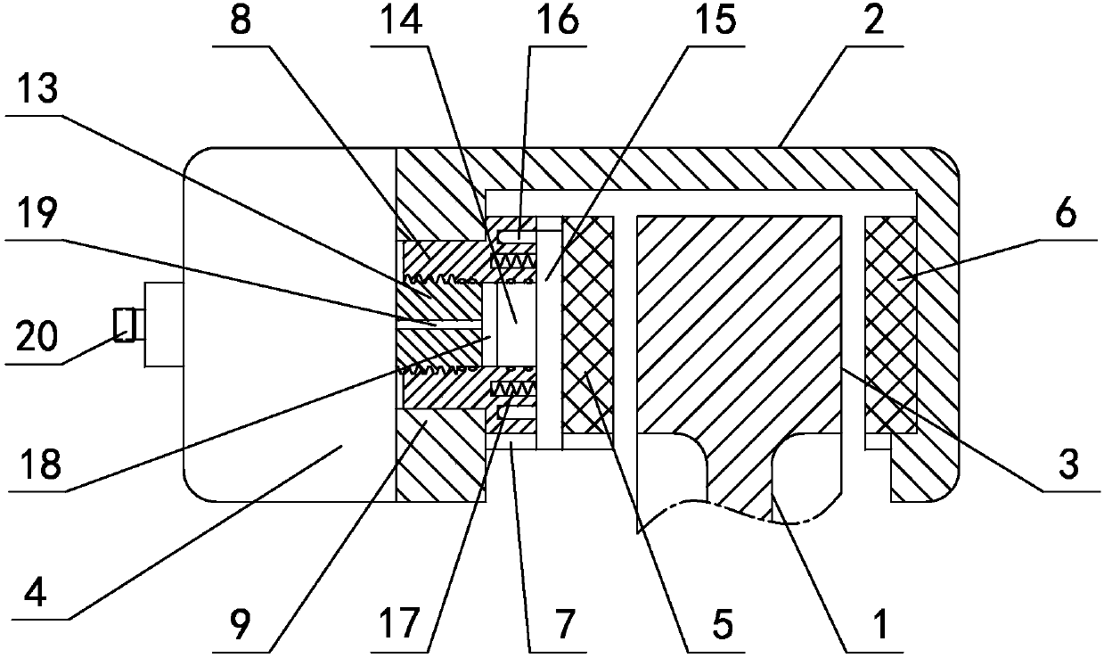
[0037] in such as figure 1 figure 2 In the shown embodiment 1, a brake device for an automobile includes a steel (magnetic material) brake disc 1 and a housing 2 arranged on the outer periphery of the brake disc and partially covering the brake disc. The cross-section of the outer edge of the moving disc is T-shaped, and the two sides of the brake disc are protrudingly provided with annular friction edges 3, and the annular friction edges are provided with textured patterns; the housing is provided with a brake motor 4 connected to the controller. The moving motor is a stepping motor, which is arranged at the upper middle position of the brake disc. The brake motor is connected with a floating caliper brake mechanism, and the caliper brake mechanism includes The movable brake pad 5 between them and the custom brake pad 6 arranged opposite to the other side of the brake disc, a top plate 7 is set between the brake motor and the dynamic brake pad, and a top block 8 is arranged...

Embodiment 2

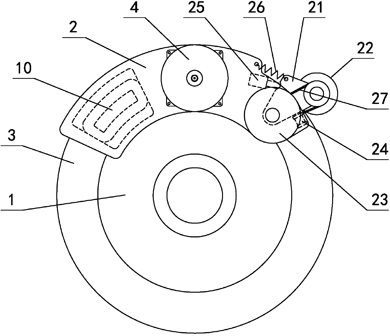
[0046] in such as image 3 Figure 4 In the shown embodiment 2, the outer circumferential surface of the brake disc is provided with a texture, the brake motor is arranged at the upper middle position of the brake disc, and a pair of electromagnetic brake blocks are provided on one side of the brake motor housing. 10. There is an auxiliary braking mechanism on the other side of the brake motor housing. The auxiliary braking mechanism includes a pair of steel (magnetic material) swing arms 21 arranged on both sides of the housing. The ends of the swing arms are connected by The bearing has a cylindrical friction wheel 22, and the housing is provided with a swing arm drive mechanism and a swing arm reset mechanism. The swing arm drive mechanism includes an electric drive mechanism and a hydraulic drive mechanism. The electric drive mechanism is arranged near the bottom of the swing arm The electromagnet 24, the hydraulic driving mechanism is a hydraulic ejector 25 arranged abov...


PUM


Abstract

The invention discloses an automobile brake device and a brake method. The cross section of the periphery of a brake disc is in a T shape, and the two faces of the brake disc are both convexly provided with annular friction edges; a shell is provided with a brake motor connected with a controller, and the brake motor is connected with a clamp type brake mechanism; an ejector plate is arranged between the brake motor and a movable brake pad, and the rear portion of the ejector plate is provided with an ejector block; the shell is provided with an ejector block sleeve matched with the ejector block, and the ejector block is arranged in the ejector block sleeve in a sliding manner; the brake motor is connected with the ejector block through a thread transmission mechanism; and when the brakemotor rotates, the ejector block moves to press or release the movable brake pad through the ejector plate. The automobile brake device can achieve active brake and rapid brake, can recycle brake energy during braking, is high in safety performance and has quite high practical value.

Description

technical field [0001] The invention belongs to the technical field of automobile manufacturing, and in particular relates to an automobile braking device and method. Background technique [0002] The braking method of the traditional automobile braking system is to apply pressure on the brake pedal by the driver, which is amplified and converted into hydraulic pressure by the vacuum booster system, and acts on the brake to achieve braking. There are disadvantages in this braking method. First, active braking cannot be realized, because the working method of the existing brake determines that the input of pedal force must be converted into hydraulic pressure before braking can be realized, and the input of pedal force It must be done by the driver; the second is that the response of the existing braking system is relatively slow, because the existing braking system can only use the brake fluid as the transmission medium of force, and the pressure exerted by the person on the...

Claims


Application Information

Patent Timeline
Patent Type & Authority Applications(China)
IPC IPC(8): F16D55/225B60T13/74F16D121/20F16D121/04
Inventor 孟川
Owner 山东丰奥工程机械制造有限公司
Features
  • R&D
  • Intellectual Property
  • Life Sciences
  • Materials
  • Tech Scout
  • Unparalleled Data Quality
  • Higher Quality Content
  • 60% Fewer Hallucinations
Learn More