
Dedusting and drying device for LED lamp

A technology of LED lights and drying equipment, which is applied in the direction of dust removal, drying gas arrangement, lighting and heating equipment, etc., can solve the problems of inability to guarantee dust removal effect, cumbersome workload, and reduce the service life of LED lights, etc., to achieve dust removal and drying effects Better, uniform dust collection, good dust removal effect

Inactive Publication Date: 2018-04-17
TIANJIN TIANXING ELECTRONICS
View PDF0 Cites 0 Cited by
  • Summary
  • Abstract
  • Description
  • Claims
  • Application Information

AI Technical Summary

Problems solved by technology

[0003] 1. After the production and assembly process of the LED lamp is completed, since the entire process and the final assembly process will inevitably directly or indirectly contact the external environment, the surface of the LED lamp will be covered with dust, etc., so it needs to be completed one by one after assembly. Dust removal treatment, this process not only has a cumbersome workload and increases the labor intensity of workers, but also cannot guarantee that each LED can have a good dust removal effect
[0004] 2. During the long-term use of LED lights, due to the existence of a large amount of dust in the air, these dusts will be adsorbed on the LED lights, which not only affects the lighting effect and aesthetics of the LED lights, but also causes the dust caused by the LED lights when they are in use. The electrostatic effect even causes damage to the LED lamp, which reduces the service life of the LED lamp and increases the cost
[0005] 3. The position of the existing LED lamps during the dust removal process is mostly fixed, so it is difficult to ensure that the LED lamps are all-round without dead ends and dust removal, resulting in poor cleaning effect

Method used


Image

  • Dedusting and drying device for LED lamp
  • Dedusting and drying device for LED lamp
  • Dedusting and drying device for LED lamp

Examples


Embodiment Construction

[0025] In order to better understand the present invention, the present invention will be further described below in conjunction with specific embodiments and accompanying drawings.

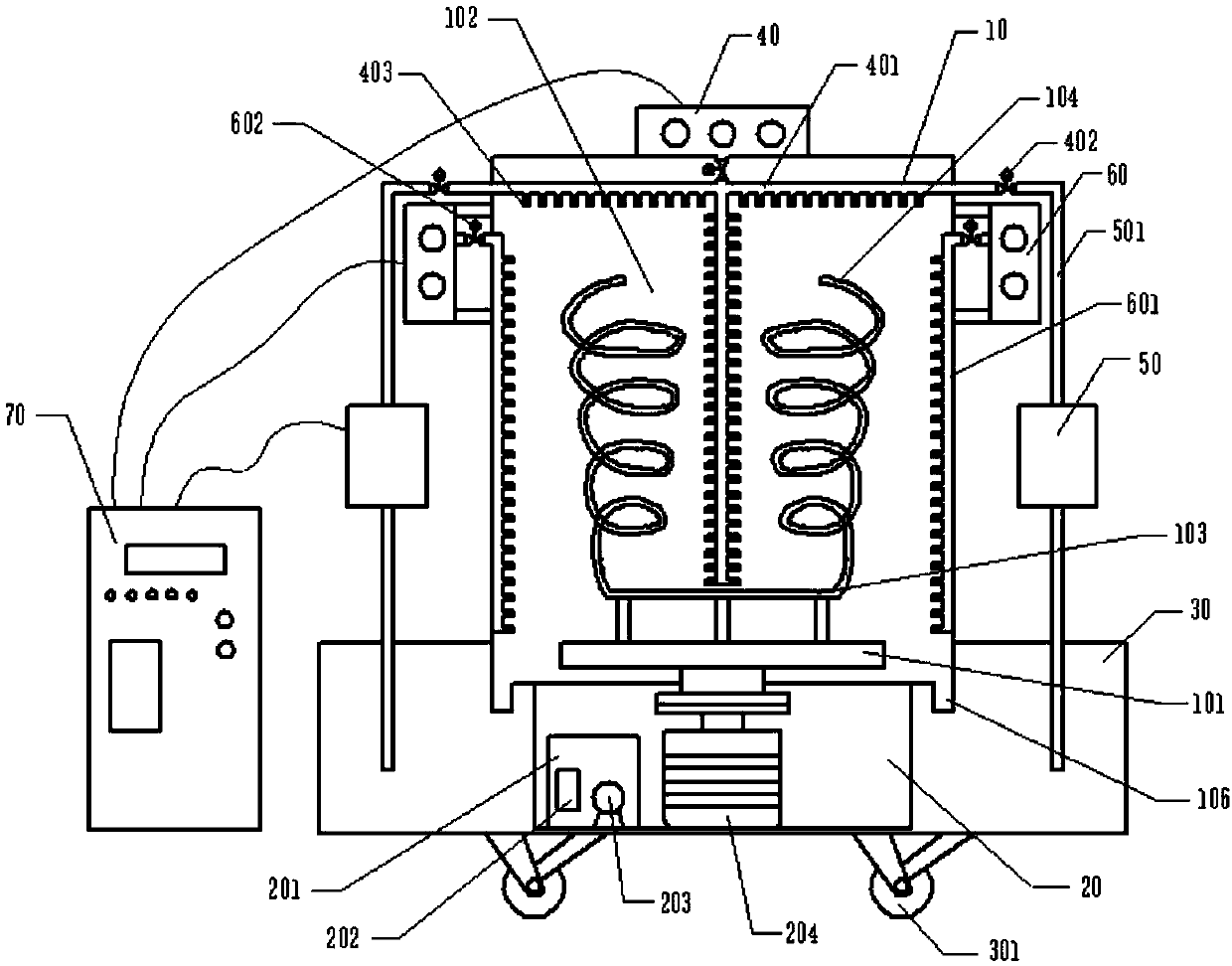
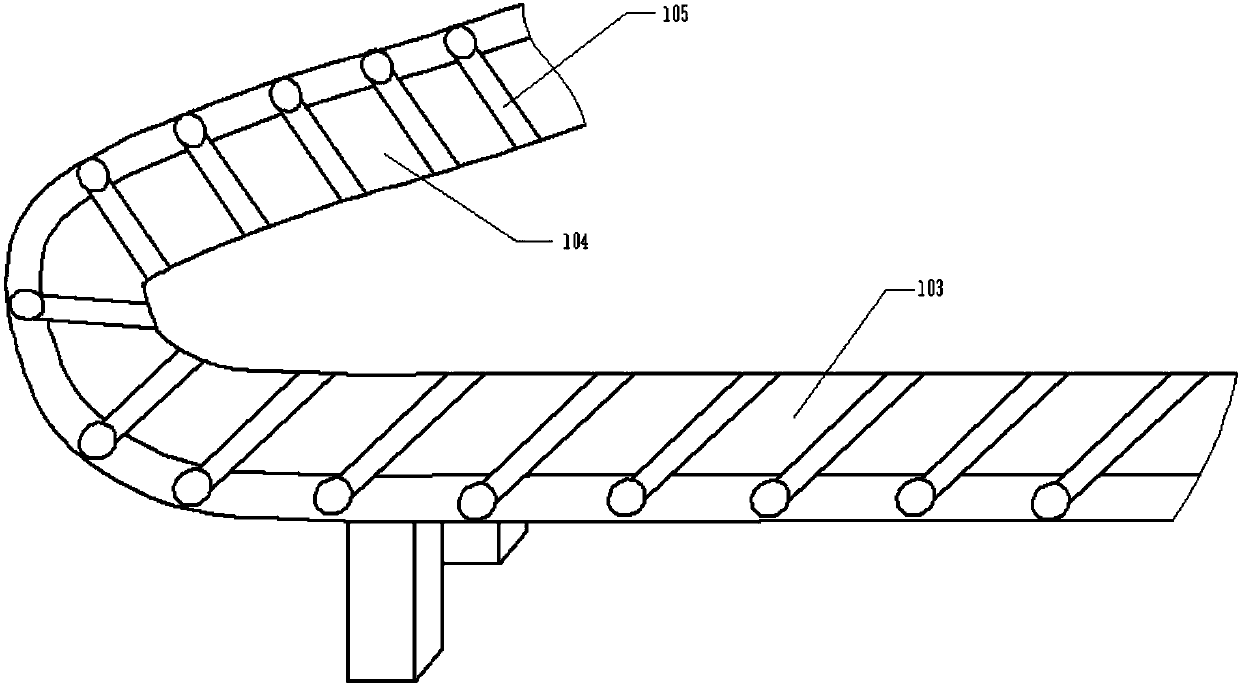
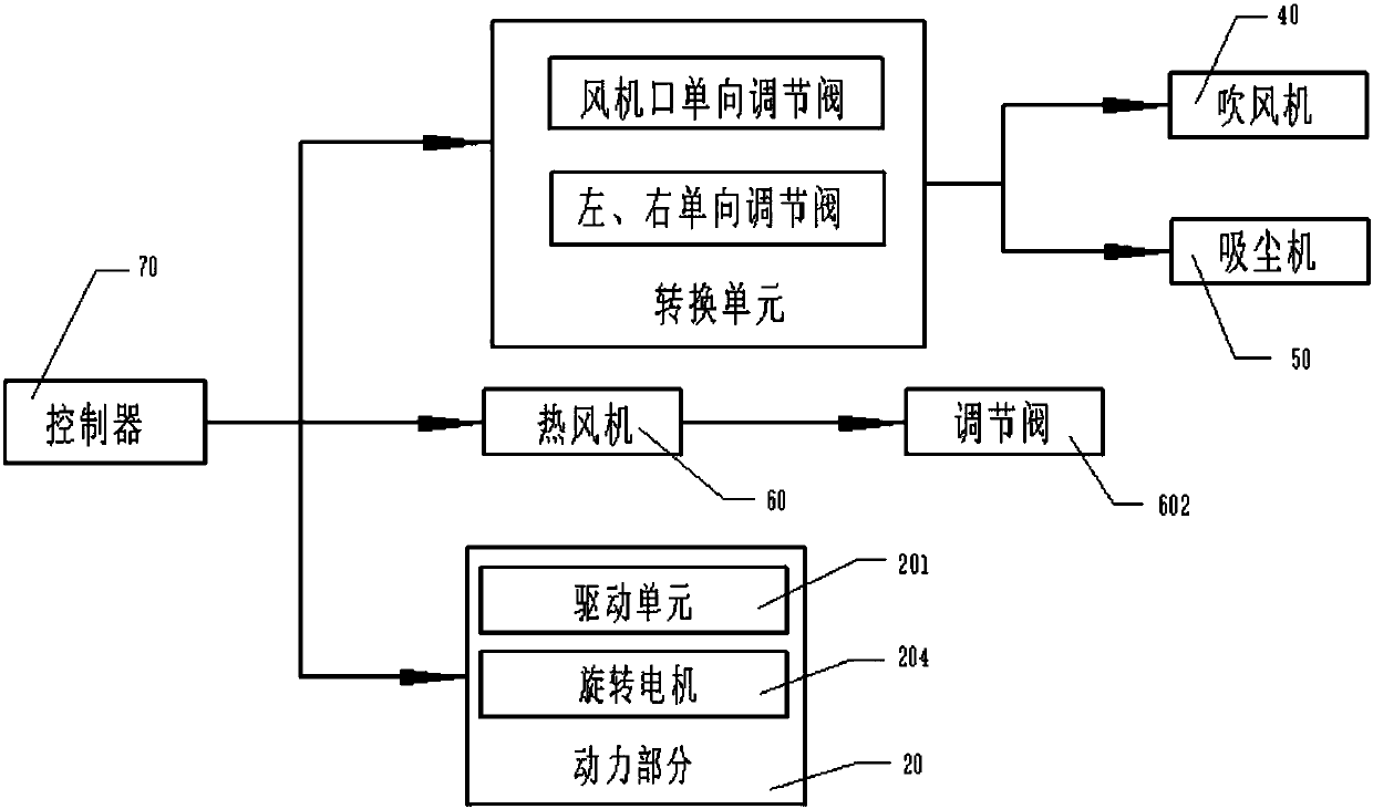
[0026] Such as Figure 1-Figure 3 As shown, a dust removal and drying equipment for LED lamps includes a dust removal device body 10, a power part 20, a dust collection box 30, a blower 40, a vacuum cleaner 50, a hot air blower 60 and a controller 70. The bottom of the dust removal device body 10 is set The power part 20, the dust collection box 30, and the blower 40 are arranged on the top of the dust removal device body 10, and the left and right sides of the dust removal device body 10 are provided with a vacuum cleaner 50 and a hot air blower 60, and the hot air blower 60 is set to be communicated through a heat pipeline 601 The inner cavity of the dust removal device body 10, the power part 20, the blower 40, the vacuum cleaner 50 and the hot air blower 60 are all set to be electrically conn...


PUM


Abstract

The invention provides a dust removal and drying device for an LED lamp. Including the dust removal device body, power part, dust collection box, blower, vacuum cleaner, hot air blower and controller, a rotating platform is set at the bottom of the inner cavity of the dust removal device body, and a storage rack is set on the rotating platform, and the storage rack is set as A structure in which the horizontal storage rack connects the left and right hovering storage racks. Both sides of the horizontal storage rack and the left and right hovering storage racks are provided with slide rails. On the slide rails, a plurality of slide bars are set by sliding the sliders. The slide bars are set as Driven by the drive unit to slide back and forth, the blower and the vacuum cleaner are set to be connected to the body of the dust removal device through pipelines, the pipeline is set to include the blowing and dust suction pipe section and the dust suction pipe section, and the blower and vacuum cleaner are set to share blowing, Dust section. The present invention adopts the dedusting equipment, which can achieve good dedusting and uniform and fast drying of LED lamps in batches, so that the surface of the LED lamps can be effectively cleaned after the assembly process is completed or after long-term use, and the service life of the LED lamps can be prolonged.

Description

technical field [0001] The invention relates to the technical field of auxiliary equipment for LED lamps, in particular to a dust removal and drying equipment for LED lamps. Background technique [0002] Nowadays, with the enhancement of people's awareness of energy saving and environmental protection, the selection of daily necessities tends to be more green and low energy consumption. Among them, LED is a solid-state semiconductor device, which can directly convert electrical energy into light energy. As a new generation of solid cold light source, LED light color is soft, bright and colorful, and it has low loss, low energy consumption and green environmental protection. And other advantages, it is widely used for long-time lighting in homes, shopping malls, banks, hospitals, hotels, restaurants and other public places. However, existing LED lamps often have the following problems in actual production and life: [0003] 1. After the production and assembly process of th...

Claims


Application Information

Patent Timeline
Patent Type & Authority Applications(China)
IPC IPC(8): F21K9/20B08B5/02B08B15/04F26B21/00
CPCB08B5/02B08B15/04F26B21/00
Inventor 彭天原石海莲王蔚王红杨世健张来顺
Owner TIANJIN TIANXING ELECTRONICS
Learn More