Experimental use multi-row pressure testing rake device

A pressure measurement rake and experimental technology, which is applied in the field of fluid mechanics experimental test equipment, can solve the problems of test data interference, spatial resolution limitation, and limited application, so as to achieve small flow field interference, accurate test data, and improve spatial resolution Effect

Active Publication Date: 2018-04-17
INST OF HIGH SPEED AERODYNAMICS OF CHINA AERODYNAMICS RES & DEV CENT
View PDF6 Cites 14 Cited by
  • Summary
  • Abstract
  • Description
  • Claims
  • Application Information

AI Technical Summary

Problems solved by technology

[0004] There are three main deficiencies in the traditional pressure measurement rake experimental device. First, due to the thickness of the pipe wall of the ventilation pipe, the outer diameter of the ventilation pipe is larger than its inner diameter, so the minimum interval between adjacent ventilation pipes is the outer diameter of the circular pipe, which leads to The spatial resolution of the velocity distribution in the boundary layer area measured by the rake is limited by the outer diameter of the circular tube; second, the distance between the air tubes of the traditional pressure measurement rake cannot be obtained, otherwise the air tubes will interfere with each other's test data, further limiting the test The improvement of the spatial resolution of the data, and the third is that the rectangular windward surface of the traditional pressure rake interferes with the flow field, which affects the accuracy of the test data of the pressure rake
Therefore, the traditional pressure rake experimental device limits the improvement of the spatial resolution of the velocity distribution of the boundary layer, and also limits the application of the pressure rake experimental device in the layout optimization design of buried weapon bays, aircraft inlets and other equipment.

Method used


Image

  • Experimental use multi-row pressure testing rake device
  • Experimental use multi-row pressure testing rake device
  • Experimental use multi-row pressure testing rake device

Examples


Embodiment 1

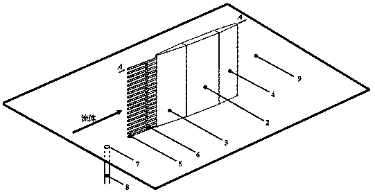
[0058] A multi-row pressure measurement rake device for experiments, installed on the surface of the model 9 to be tested, the multi-row pressure measurement rake device includes a plurality of single-row pressure measurement rakes, and the single-row pressure measurement rakes are distributed and installed on the model to be tested In the area where the velocity distribution of the boundary layer on the surface of 9 is the same, adjacent single rows of pressure measuring rakes are distributed along the spanwise direction of the surface of the model to be tested 9; the single row of pressure measuring rakes is provided with a total pressure discharge pipe 5, and The pipe 5 is composed of a row of vertically arranged ventilation pipes facing the direction of the fluid. The diameter of the ventilation pipes is D; the ventilation pipes are fixedly separated by a spacing adjustment block 6, and the height of the spacing adjustment block 6 is H; a separation block is arranged betwee...

Embodiment 2

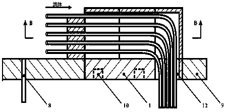
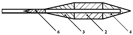
[0064] This embodiment is further optimized on the basis of embodiment 1, as figure 1 As shown, the multi-row pressure measurement rake device includes a single-row test rake; the single-row test rake includes a connection base 1 and a front edge rectification fixedly arranged on the connection base 1 in sequence, a main body rectification base 2, and a rear edge rectifier base 4; as figure 2 As shown, the connecting base 1 is fixedly embedded in the surface of the model to be measured 9 by connecting screws 10, and the surface of the connecting base 1 is flush with the surface of the model to be measured 9;

[0065] The connection base 1 may be provided with a through exhaust pipe outlet 12, and one end of the total pressure exhaust pipe 5 passes through the cavity formed by the front edge rectification base 3, the main body rectification base 2, and the rear edge rectification base 4 in sequence. Pass through the discharge pipe outlet 12 of the connection base 1; the other...

Embodiment 3

[0071]This embodiment is further optimized on the basis of embodiment 2, as Figure 4 As shown, the multiple rows of pressure measuring rakes include a single row of pressure measuring rakes R 1 and single-row pressure rake R 2 , single row pressure measuring rake R 1 and single-row pressure rake R 2 It is distributed along the surface span of the model 9 to be tested, and the interval between the single row of pressure measuring rakes is 1.5 times the thickness of the boundary layer; the single row of pressure measuring rakes R 1 The air pipe of the air pipe is directly set close to the surface of the model 9 to be tested; the single row of pressure measuring rakes R 2 The bottom end of the total pressure exhaust pipe 5 is connected to the surface of the model 9 to be tested through the partition block 11, and the height of the partition block 11 is (H+D) / 2, where H is the height of the spacing adjustment block 6; then the calculation is:

[0072]

[0073] When the mul...


PUM


Abstract

The invention discloses an experimental use multi-row pressure testing rake device arranged on the surface of a to-be-tested model and comprising a plurality of single-row pressure testing rakes witha rectification effect; the single-row pressure testing rakes are distributed and mounted on the areas of the surface of the to-be-tested model, wherein said areas are same in boundary layer speed distribution; the adjacent single-row pressure testing rakes are distributed on the surface of the to-be-tested model in a spanwise manner; the single-row pressure testing rake comprises a total pressuretube bank formed by breather pipes in a row; isolation blocks are arranged between the total pressure tube bank and the to-be-tested model, and the heights of the isolation blocks are arranged in a graded distribution along with the single-row pressure testing rake distribution. Compared with a conventional pressure testing rake experiment device, the effective measuring point interval is smaller, thus obtaining more test data in a unit length, and effectively improving the spatial resolution in the boundary layer measurement; the experimental use multi-row pressure testing rake device can reduce the interferences caused by the single-row pressure testing rake geometry profile on the flow field, and thus providing more accurate test data.

Description

technical field [0001] The invention belongs to the technical field of fluid mechanics experiment testing devices, and in particular relates to a multi-row pressure measuring rake device for experiments. Background technique [0002] When a fluid such as air or water flows over the surface of an object, there is always a thin layer of uneven velocity distribution near the surface of the object, which is called the boundary layer. In the region inside the boundary layer, the fluid viscosity plays a dominant role, and in the region outside the boundary layer, the influence of fluid viscosity is weak. The research results show that the velocity distribution of the flow field area inside the boundary layer has an important impact on the entire space flow field, and is related to the optimization of the layout scheme of the buried weapon bay, the aircraft inlet, etc., and the improvement of equipment performance. Therefore, the velocity distribution of the boundary layer area Ve...

Claims


Application Information

Patent Timeline
Patent Type & Authority Applications(China)
IPC IPC(8): G01M9/06
CPCG01M9/065
Inventor 王显圣施傲周方奇刘俊杨党国吴军强高荣钊别炎华梁锦敏杨可杨野
Owner INST OF HIGH SPEED AERODYNAMICS OF CHINA AERODYNAMICS RES & DEV CENT
Why Eureka
Try Eureka