An outdoor high protection distribution box

A distribution box, high protection technology, applied in the substation/distribution device shell, electrical components, substation/switch layout details, etc., can solve the problems of being susceptible to scratches and affecting the internal work of the distribution box, so as to prevent long-term The effect of time soaking

Active Publication Date: 2019-04-02
JIANGSU JIANXIONG ELECTRIC CO LTD
View PDF1 Cites 2 Cited by
  • Summary
  • Abstract
  • Description
  • Claims
  • Application Information

AI Technical Summary

Problems solved by technology

[0002] At present, no matter in daily life or in industrial production, in order to ensure the safety of electricity consumption, people pay more and more attention to the monitoring of circuit operation. The existing monitoring methods for circuit operation are generally It is directly aimed at the transformation of the original electrical circuit, and it is realized by connecting the corresponding electrical components for detecting current or voltage in the circuit. For example, when monitoring whether the circuit is overloaded, a Ammeter, the greater the current detected by the ammeter, the more loads in the circuit. In the prior art, such as the invention patent with application number 201620149305.3, the main body of the distribution box; Switch state sensing device, controller, input / output module; the switch state sensing device is used to generate an induction electrical signal according to the state of the switch installed in the main body of the distribution box; the switch state sensing device is physically separated from the switch; the controller is used to The electrical signal judges the switching status of the switch and generates the switching status electrical signal; the input / output module is used to output the switching status electrical signal. Although this patent can monitor the circuit, the general distribution box is placed outdoors and is easily scratched. In severe cases, it may affect the internal work of the distribution box

Method used


Image

  • An outdoor high protection distribution box
  • An outdoor high protection distribution box
  • An outdoor high protection distribution box

Examples


Embodiment Construction

[0023] The following will clearly and completely describe the technical solutions in the embodiments of the present invention with reference to the accompanying drawings in the embodiments of the present invention. Obviously, the described embodiments are only some, not all, embodiments of the present invention. Based on the embodiments of the present invention, all other embodiments obtained by persons of ordinary skill in the art without making creative efforts belong to the protection scope of the present invention.

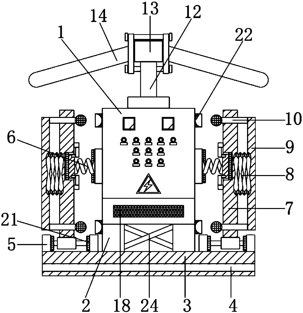
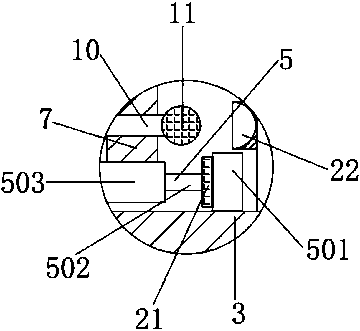
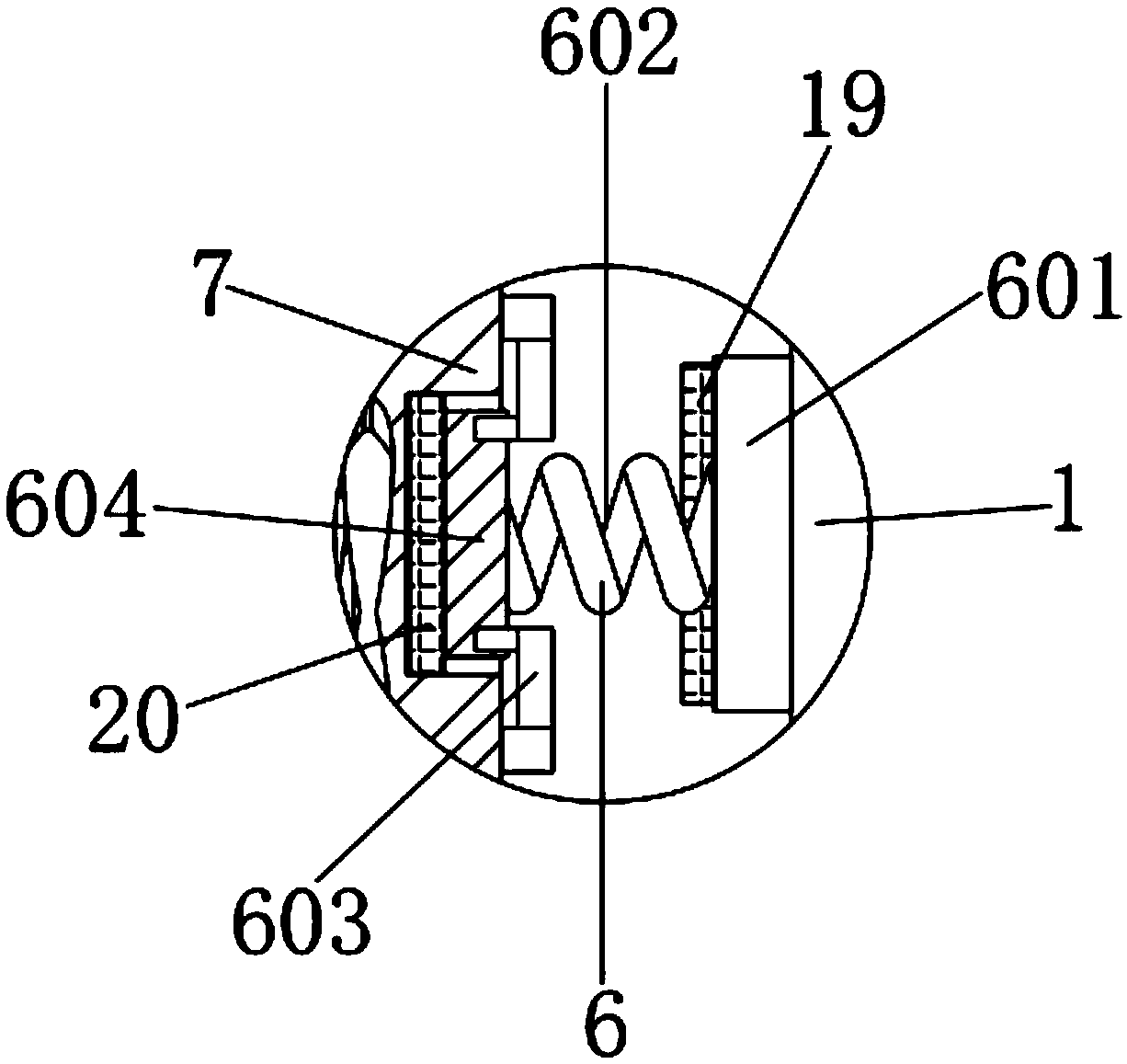
[0024] see Figure 1-4, the present invention provides a technical solution: an outdoor high-protection distribution box, including a distribution box 1, the distribution box 1 is a large number of parameters on the data, and generally constitutes a low-voltage forest according to electrical wiring, requiring the switchgear, measurement Instruments, protective appliances and auxiliary equipment are assembled in a closed or semi-closed metal cabinet or on a scr...


PUM


Abstract

The invention discloses an outdoor high-protection-level distribution box. The distribution box comprises a distribution box body, a heat radiation chamber is mounted in the bottom end of the distribution box body, supporting legs are mounted in left and right sides of the bottom end of the heat radiation chamber, a slide bar is mounted between internal centers of slide bar blocks, a second baffleplate penetrates a first baffle plate via a first pole, a rubber block is mounted in the internal end portion of the first pole, and the internal side of a first spring is connected to the distribution box body via a side block. A buffering device cooperates with the first baffle plate, so that the first spring is fixed to the outer side of the distribution box body via the side block, a connection block is popped outwardly via characteristics of the first spring, a force conducted from the first baffle plate can be buffered, the buffering device realizes a high protection effect, the distribution box is collided less outdoor, and damage of the distribution box outdoor is reduced.

Description

technical field [0001] The invention relates to the technical field of electric equipment, in particular to an outdoor high-protection distribution box. Background technique [0002] At present, no matter in daily life or in industrial production, in order to ensure the safety of electricity consumption, people pay more and more attention to the monitoring of circuit operation. The existing monitoring methods for circuit operation are generally It is directly aimed at the transformation of the original electrical circuit, and it is realized by connecting the corresponding electrical components for detecting current or voltage in the circuit. For example, when monitoring whether the circuit is overloaded, a Ammeter, the greater the current detected by the ammeter, the more loads in the circuit. In the prior art, such as the invention patent with application number 201620149305.3, the main body of the distribution box; Switch state sensing device, controller, input / output mod...

Claims


Application Information

Patent Timeline
Patent Type & Authority Patents(China)
IPC IPC(8): H02B1/46H02B1/56H02B1/28H02B1/54
CPCH02B1/28H02B1/46H02B1/54H02B1/565
Inventor 孙笛
Owner JIANGSU JIANXIONG ELECTRIC CO LTD
Why Eureka
Try Eureka