Control method of quasi-virtual synchronous machine

A technology of virtual synchronous machine and control method, applied in the direction of reducing/preventing power oscillation, single-network parallel feeding arrangement, converting AC power input to DC power output, etc., can solve problems such as insufficient damping, failure, power oscillation, etc., and achieve Easy power sharing, easy to implement, and achieve the effect of power sharing

Inactive Publication Date: 2018-04-17
北京科诺伟业科技股份有限公司
View PDF3 Cites 8 Cited by
  • Summary
  • Abstract
  • Description
  • Claims
  • Application Information

AI Technical Summary

Problems solved by technology

[0004] The present invention aims at the defect that the damping characteristic of the existing virtual synchronous machine becomes invalid when the primary frequency modulation is disabled in grid connection, and proposes a quasi-virtual synchronous machine control method
Solved the problem of power oscillation caused by insufficient damping when the virtual synchronous machine is connected to the grid

Method used


Image

  • Control method of quasi-virtual synchronous machine
  • Control method of quasi-virtual synchronous machine
  • Control method of quasi-virtual synchronous machine

Examples


Embodiment Construction

[0037] The present invention will be further described below in conjunction with the drawings and specific embodiments.

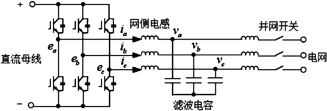
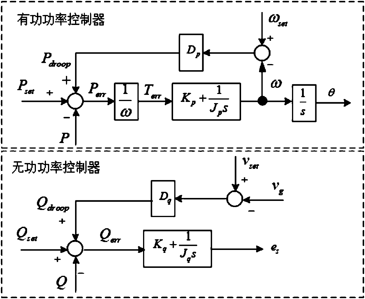
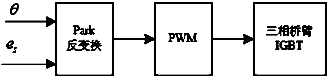
[0038] Such as figure 1 As shown, the DC bus end of the virtual synchronous machine is connected to the energy storage unit, and the three-phase bridge arm of the power unit is connected to the grid through a filter loop composed of LC. The control block diagram of the paravirtual synchronous machine of the present invention is as follows figure 2 As shown, the upper part of the figure is the active power controller with the active power loop PI regulator as the core, and the lower part of the figure is the reactive power controller with the reactive power loop PI regulator as the core. The two controllers respectively generate modulation The angle and amplitude information of the voltage. The angle and amplitude information of the modulation voltage is image 3 After the Park inverse conversion is shown, modulation is performed to drive the three-phase brid...


PUM


Abstract

A control method of a quasi-virtual synchronous machine comprises the steps of connecting a proportional controller in parallel with an inertial link of a virtual synchronous machine to form an activepower loop PI regulator and a reactive power loop PI regulator, converting characteristic of an original integral regulator to characteristic of the PI regulator, generating angle information of thevirtual synchronous machine by an active power controller taking the active power loop PI regulator as a core, generating voltage amplitude information of the virtual synchronous machine by a reactivepower controller taking the reactive power loop PI regulator as a core, and modulating to drive a three-phase bridge-arm insulated gate bipolar transistor (IGBT) to act after Park reverse conversionon the angle information and the amplitude information. Indifference control of an active power and a reactive power can be achieved during grid-connected running and when the voltage amplitude and the frequency of a power grid are normal, inertia and a primary regulation function can be provided when the power grid amplitude and the frequency are abnormal, and power equalization can be easily achieved during off-grid running.

Description

Technical field [0001] The invention relates to a control method of a pseudo-virtual synchronous machine, in particular to a control method of a pseudo-virtual synchronous machine with an active power loop PI regulator and a reactive power loop PI regulator. Background technique [0002] In recent years, with the rapid development of distributed renewable energy and microgrid, the virtual synchronous machine control technology that virtualizes the converter into a synchronous generator can make the converter present a voltage source with inertia and damping characteristics. Widespread concern. However, as a power electronic device, the converter's ability to withstand transient power fluctuations and short-term overload is very limited, which can cause system oscillations, and damage to converter equipment. [0003] The existing virtual synchronous machine controller usually needs to adjust the damping parameter in order to reduce the power oscillation. "CN201610474093-Virtual Sy...

Claims


Application Information

Patent Timeline
IPC IPC(8): H02J3/38H02J3/24H02M7/5387
CPCH02J3/24H02J3/38H02J3/388H02J2203/20H02M7/5387
Inventor 董志然许洪华
Owner 北京科诺伟业科技股份有限公司
Why Eureka
Try Eureka