Torque motor units for valve positioners

A valve positioner and torque motor technology, applied in the field of torque motor devices, can solve the problems of permanent deformation of hinges, shortened service life of electric-electric conversion devices, and twisted hinges due to strong gravitational force, so as to achieve easy rotation, improve durability, and improve service life. Effect

Active Publication Date: 2020-02-21
株式会社チシン
View PDF1 Cites 0 Cited by
  • Summary
  • Abstract
  • Description
  • Claims
  • Application Information

AI Technical Summary

Problems solved by technology

In the prior art, although there is a technical application in which the moving part acting on the opening and closing baffle of the nozzle is rotated through the electro-pneumatic conversion device, the magnetism of the moving part is caused by the permanent magnet arranged under one end of the moving part. , the moving part in this way is strongly attracted by the permanent magnet, which leads to unnecessary strong gravitational distortion of the hinge fixing the moving part, which will cause permanent deformation of the hinge as the use time increases
This shortcoming makes the service life of the electro-pneumatic conversion device significantly reduced, and it is difficult to set the initial position of the floating member. It is necessary to improve the aforementioned shortcoming in the prior art

Method used


Image

  • Torque motor units for valve positioners
  • Torque motor units for valve positioners
  • Torque motor units for valve positioners

Examples


Embodiment Construction

[0030] In order to further explain the technical means and effects of the present invention to achieve the intended purpose of the invention, the specific implementation methods and steps of the torque motor device for valve positioners proposed according to the present invention will be described below in conjunction with the accompanying drawings and preferred embodiments. , structure, characteristics and functions in detail.

[0031] Refer to the following Figure 1 to Figure 4 , which is a torque motor device for a valve positioner according to an embodiment of the present invention in detail.

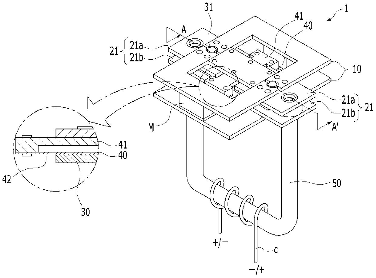
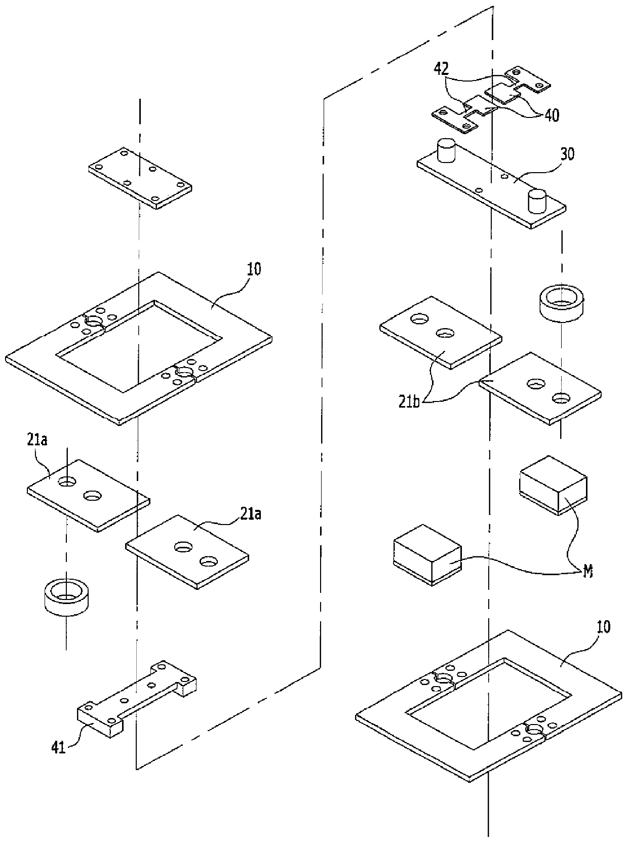
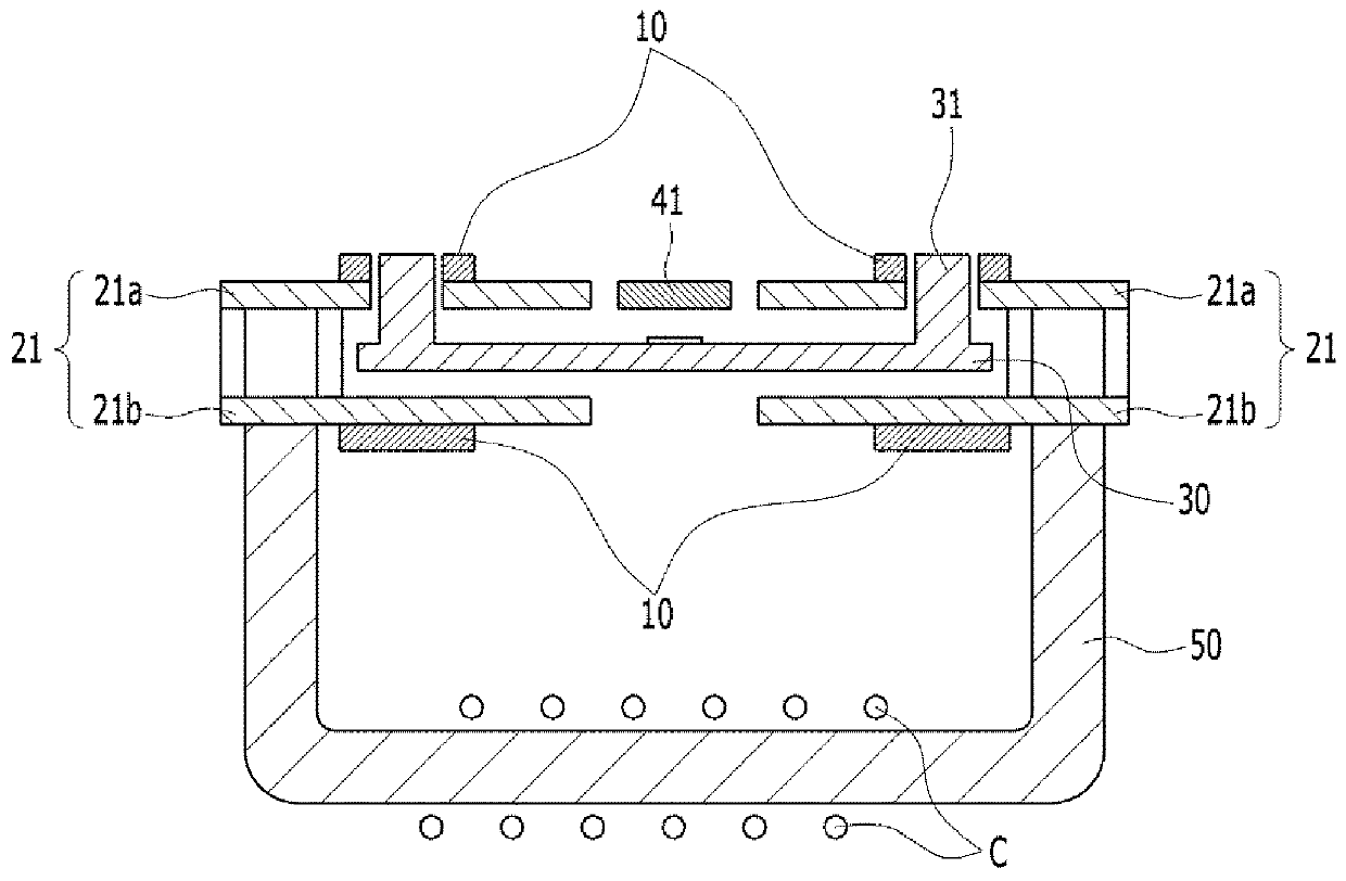
[0032] See Figure 1 to Figure 4 As shown, the present invention is used for a torque motor device embodiment of a valve positioner, a three-dimensional schematic diagram, an exploded three-dimensional schematic diagram, an A-A' sectional schematic diagram, and a partially enlarged schematic diagram.

[0033] A torque motor device 1 for a valve positioner according to an embodime...


PUM


Abstract

The invention relates to a torque motor device for a valve positioned. The device includes a pair of magnetized metal pieces having opposite polarities after magnetization and arranged in a spaced andparallel manner; a movable piece whose two ends disposed between the metal pieces in a pair and capable of rotating about a hinge part arranged between the two ends; a stator generating a magnetic field through current so as to magnetize the movable piece, wherein the movable piece is arranged on a magnetic line generated by the stator. According to the invention, valve action can be controlled and regulated more easily and the service lifetime of the device is long.

Description

technical field [0001] The invention relates to a torque motor device for a valve positioner which converts electric current into kinetic energy to control the opening and closing of a nozzle, in particular to a pneumatic position controller which can adjust the action of the control valve through a small current and improve durability Torque motor units for valve positioners. Background technique [0002] In pneumatic control devices or pneumatic regulator products, the technology of converting tiny electrical signals into pneumatic signals is often used. An example of using this principle is to control the displacement of the nozzle opening and closing baffle through electrical signals to adjust the distance between the nozzle and the nozzle opening and closing baffle, thereby controlling the opening and closing of the nozzle. That is, when an electrical signal is input, the current is converted into a mechanical rotational force similar to the baffle control device, and ...

Claims


Application Information

Patent Timeline
Patent Type & Authority Patents(China)
IPC IPC(8): H02K26/00F16K31/04
CPCF16K31/04H02K26/00H01F7/145
Inventor 李镛熙
Owner 株式会社チシン
Why Eureka
Try Eureka