Digital signal isolator

A digital signal and isolator technology, applied in impedance networks, electrical components, multi-terminal-pair networks, etc., can solve the problems of high cost and high power consumption, and achieve the effect of improving withstand voltage, avoiding false triggering, and simple structure

Active Publication Date: 2018-04-17
天津智模科技有限公司
View PDF2 Cites 15 Cited by
  • Summary
  • Abstract
  • Description
  • Claims
  • Application Information

AI Technical Summary

Problems solved by technology

However, because it uses high-frequency pulses to send low-frequency data when transmitting data, it has large power consumption and high cost, and there are certain limitations.

Method used


Image

  • Digital signal isolator
  • Digital signal isolator
  • Digital signal isolator

Examples


Embodiment Construction

[0044] In order to make the technical solutions and advantages of the present invention clearer, the present invention will be further described in detail below in conjunction with the accompanying drawings and specific embodiments.

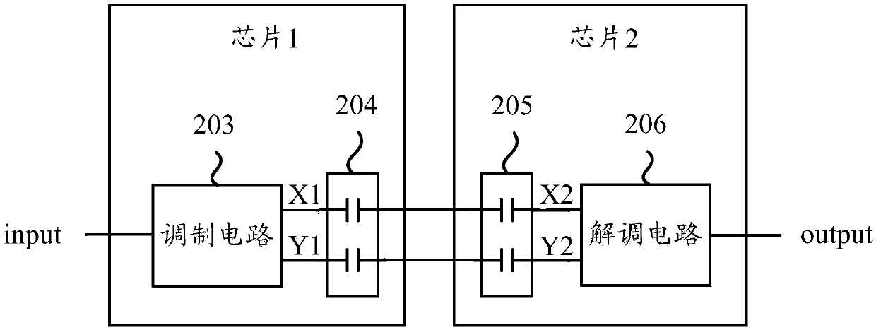
[0045] The present invention proposes a digital signal isolator based on double isolation barrier capacitance. As a dual-port device, complete electrical isolation is realized between the input port and the output port of the digital signal isolator due to the existence of the internal isolation barrier capacitance. The coupling effect of the isolation barrier capacitance completes the signal transmission.

[0046] image 3 It is a schematic structural diagram of a digital signal isolator in an embodiment of the present invention. Such as image 3 As shown, the digital signal isolator in the embodiment of the present invention includes: a sending end 301 and a receiving end 302;

[0047] The sending end 301 includes: a filter circuit 303, a re...


PUM


Abstract

The invention provides a digital signal isolator comprising a sending terminal and a receiving terminal. The sending terminal comprises a filtering circuit, a refresh circuit, a delay circuit, a refresh and pulse combination circuit, a differential signal conversion circuit, a first isolation gate capacitor and a second isolation gate capacitor; the receiving terminal comprises a third isolation gate capacitor, a fourth isolation gate capacitor, a hysteresis comparator, a watchdog circuit, a filtering circuit and an or gate. The digital signal isolator disclosed in the invention is capable ofkeeping an electric level unchanged for a long time even when low speed signals are transmitted, the digital signal isolator can be prevented from interference from a common mode electric level, and problems of false triggering can be effectively prevented.

Description

technical field [0001] The invention relates to the technical field of digital signal transmission, in particular to a digital signal isolator based on double isolation barrier capacitance. Background technique [0002] Isolation is a hot topic today, and it is of great significance to study isolation and isolated devices. There are multiple sets of ground wires in many current systems, and the ground wire loop will have a large current passing through it, so it will bring a lot of noise, and it will affect the system performance and may burn the system components. In order to prevent the occurrence of the above-mentioned problems, an isolation method is generally adopted in the prior art to solve them. Secondly, the manual operation control interface sometimes wants to be isolated from the system execution end. On the one hand, there may be a high-voltage dangerous environment at the system execution end, and on the other hand, it is also to reduce circuit instability caus...

Claims


Application Information

Patent Timeline
Patent Type & Authority Applications(China)
IPC IPC(8): H03H7/52
CPCH03H7/004H03H7/52
Inventor 不公告发明人
Owner 天津智模科技有限公司
Why Eureka
Try Eureka