Restrictors using venturi effect

A technology of restricting devices and cones, applied in the direction of brake transmission, pipeline arrangement, pump/compressor arrangement, etc., can solve problems such as engine calibration offset

Active Publication Date: 2018-04-17
DAYCO IP HLDG
View PDF9 Cites 0 Cited by
  • Summary
  • Abstract
  • Description
  • Claims
  • Application Information

AI Technical Summary

Problems solved by technology

[0005] This flow creates a potential shift in engine calibration as this gas flow can vary due to the pressure drop between the crankcase and intake manifold

Method used


Image

  • Restrictors using venturi effect
  • Restrictors using venturi effect
  • Restrictors using venturi effect

Examples


Embodiment Construction

[0022] While the following detailed description sets forth the general principles of the invention, examples of the invention are additionally illustrated in the accompanying drawings. In the drawings, like reference numbers refer to identical or functionally similar elements.

[0023] As used herein, "fluid" refers to any liquid, suspension, colloid, gas, plasma, or combination thereof.

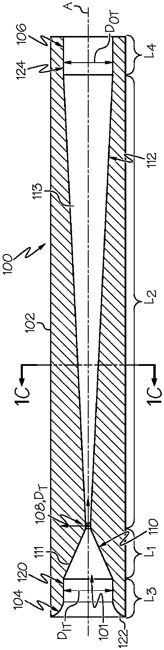
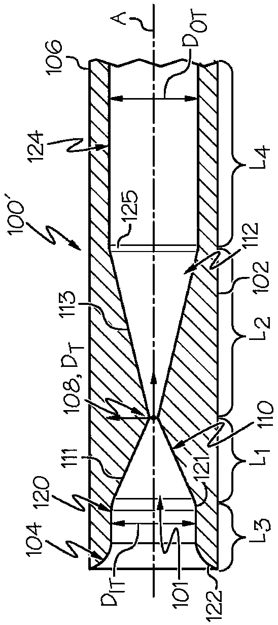
[0024] Figure 1A to Figure 2B Including restricting devices 100, 100', 200 and 200', which have superior results and require less material (with cheaper material costs) to provide such results because when the inlet cone 110, 210 and outlet cone 110, 210 and outlet As the cone 112, 212 transitions towards its throat 108, 208 in a parabolic or hyperbolic function, the overall length of the restriction can be reduced. Furthermore, a parabolic or hyperbolic restriction ensures an almost constant flow rate independent of the pressure drop across the restriction. This is done by ensuring that...


PUM


Abstract

Restrictors are disclosed that include a body defining a Venturi tube having a throat defining a junction of a converging inlet cone to a diverging outlet cone along a longitudinal axis thereof, and with the converging inlet cone and the diverging outlet cone each defining an inner passageway that transitions as a hyperbolic or parabolic function toward the throat.

Description

[0001] related application [0002] This application claims the benefit of U.S. Provisional Application No. 62 / 211,408, filed August 28, 2015, which is incorporated herein by reference. technical field [0003] The present application relates to restriction devices using the Venturi effect for producing a substantially constant fluid flow therethrough during operating pressure changes, and more particularly to such restriction devices for use in positive crankcase ventilation systems. Background technique [0004] Operational needs require that air and / or gases be removed from the engine crankcase. This ensures that no pressure builds up due to blowby gases passing through the engine's rings and pistons, and that fuel and water do not accumulate in the crankcase. Worldwide, there are regulations requiring crankcase gases to pass through the combustion chamber in order to minimize the release of harmful emissions. One method used to do this is to connect the crankcase to th...

Claims


Application Information

Patent Timeline
Patent Type & Authority Applications(China)
IPC IPC(8): F04F5/20F04F5/44F04F5/46B01F5/04B60T13/52B60T17/02B60T17/04A47L5/18
CPCF01M13/023F01M2013/0044F16N2270/22F01M2013/026F02M26/10F02M26/19F02M25/06F01M2013/0038F01M13/028F02M35/10222F02M35/104F02B33/00F01M2013/0005Y02T10/12
Inventor D·E·弗莱特谢尔B·M·格雷琴J·H·米勒K·汉普顿
Owner DAYCO IP HLDG
Why Eureka
Try Eureka