Cutting device used for pasture grass for feeding livestock in animal husbandry

A technology of cutting equipment and animal husbandry, applied in cutting equipment, application, agriculture, etc., can solve the problems of manpower and time consumption, insufficient cutting, economic loss, etc., and achieve good cutting effect

Inactive Publication Date: 2018-04-20
皮强义
View PDF3 Cites 11 Cited by
  • Summary
  • Abstract
  • Description
  • Claims
  • Application Information

AI Technical Summary

Problems solved by technology

[0005] In order to overcome the disadvantages of manual cutting of forage grass, it takes a lot of manpower and time, the cutting is not comprehensive enough, it cannot be air-dried in time after cutting, the forage grass is easy to mold and deteriorate, and causes economic losses. The technical problem to be solved by the invention is to provide a Cutting equipment for animal husbandry that can save manpower and time, can cut comprehensively, can be air-dried in time after cutting, and reduces economic losses

Method used


Image

  • Cutting device used for pasture grass for feeding livestock in animal husbandry
  • Cutting device used for pasture grass for feeding livestock in animal husbandry
  • Cutting device used for pasture grass for feeding livestock in animal husbandry

Examples


Embodiment 1

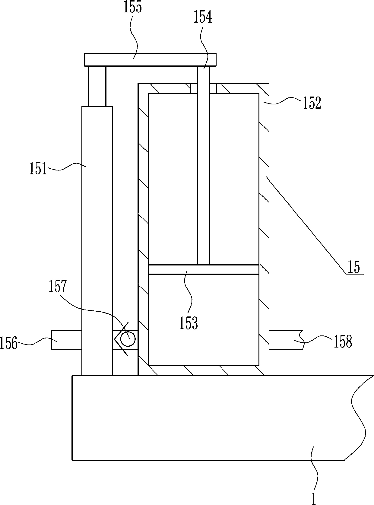
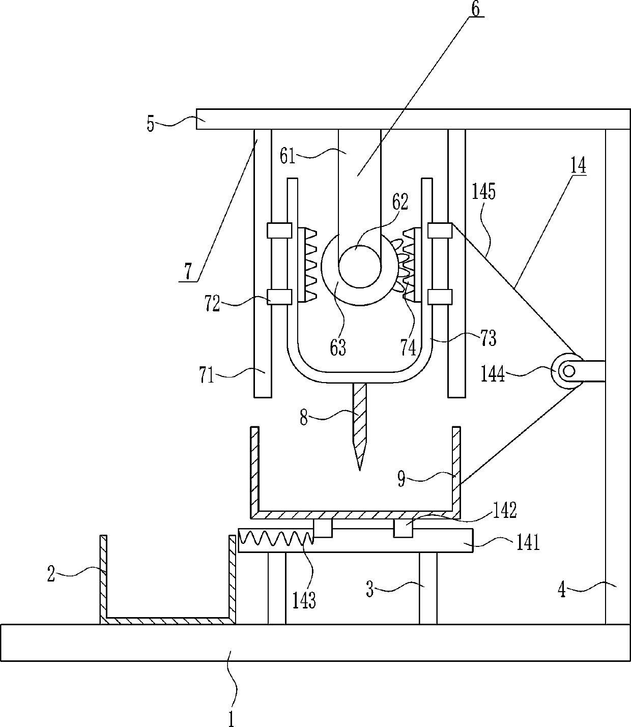
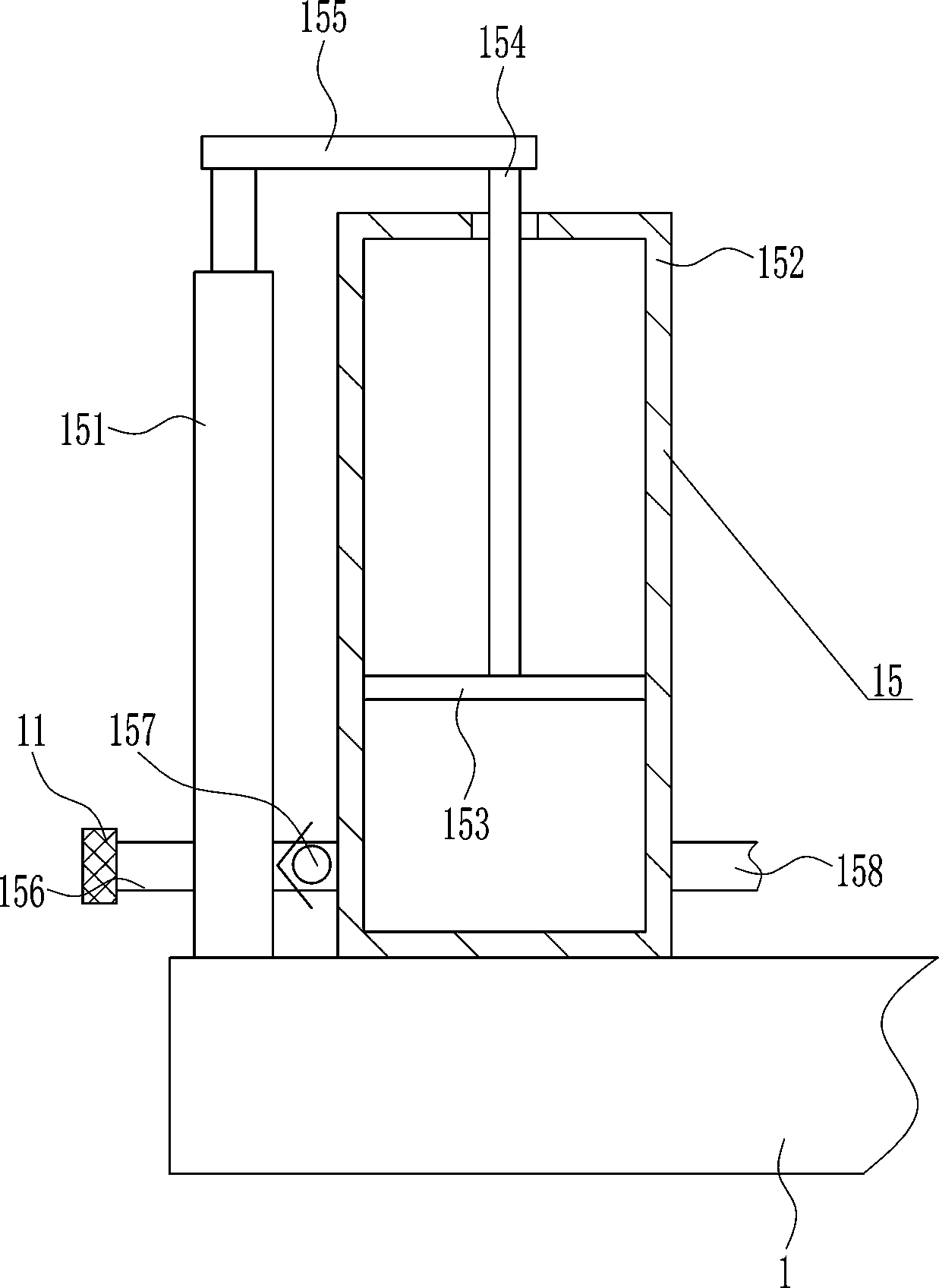
[0037] A cutting device for feeding pastures in animal husbandry, such as Figure 1-7 As shown, it includes a base plate 1, a collection frame 2, a pole 3, a bracket 4, a top plate 5, a driving device 6, a lifting device 7, a cutter 8 and a placement frame 9, and the top of the base plate 1 is connected by bolts in turn from left to right. The collection frame 2, the pole 3 and the bracket 4 are installed in the method, and the pole 3 and the bracket 4 are arranged vertically, the top of the pole 3 is connected with the placement frame 9 by bolt connection, and the top of the bracket 4 is horizontal by bolt connection. The top plate 5 is connected, the bottom left side of the top plate 5 is provided with a driving device 6, the bottom of the top plate 5 outside the driving device 6 is provided with a lifting device 7, the lifting device 7 cooperates with the driving device 6, and a cutting knife is connected to the lifting part of the lifting device 7 8. The cutter 8 is locate...

Embodiment 2

[0039] A cutting device for feeding pastures in animal husbandry, such as Figure 1-7 As shown, it includes a base plate 1, a collection frame 2, a pole 3, a bracket 4, a top plate 5, a driving device 6, a lifting device 7, a cutter 8 and a placement frame 9, and the top of the base plate 1 is connected by bolts in turn from left to right. The collection frame 2, the pole 3 and the bracket 4 are installed in the method, and the pole 3 and the bracket 4 are arranged vertically, the top of the pole 3 is connected with the placement frame 9 by bolt connection, and the top of the bracket 4 is horizontal by bolt connection. The top plate 5 is connected, the bottom left side of the top plate 5 is provided with a driving device 6, the bottom of the top plate 5 outside the driving device 6 is provided with a lifting device 7, the lifting device 7 cooperates with the driving device 6, and a cutting knife is connected to the lifting part of the lifting device 7 8. The cutter 8 is locate...

Embodiment 3

[0042] A cutting device for feeding pastures in animal husbandry, such as Figure 1-7 As shown, it includes a base plate 1, a collection frame 2, a pole 3, a bracket 4, a top plate 5, a driving device 6, a lifting device 7, a cutter 8 and a placement frame 9, and the top of the base plate 1 is connected by bolts in turn from left to right. The collection frame 2, the pole 3 and the bracket 4 are installed in the method, and the pole 3 and the bracket 4 are arranged vertically, the top of the pole 3 is connected with the placement frame 9 by bolt connection, and the top of the bracket 4 is horizontal by bolt connection. The top plate 5 is connected, the bottom left side of the top plate 5 is provided with a driving device 6, the bottom of the top plate 5 outside the driving device 6 is provided with a lifting device 7, the lifting device 7 cooperates with the driving device 6, and a cutting knife is connected to the lifting part of the lifting device 7 8. The cutter 8 is locate...


PUM


Abstract

The invention relates to a pasture grass cutting device, and particularly relates to a cutting device used for pasture grass for feeding livestock in animal husbandry. The technical problem to be solved by the invention is to provide a cutting device with which manpower and time can be saved, overall cutting can be achieved, air drying can be carried out in time after cutting, and economic loss can be reduced, wherein the cutting device is used for feeding the livestock in animal husbandry. In order to solve the technical problems, the invention provides the cutting device for the pasture grass for feeding the livestock in animal husbandry. The cutting device comprises a bottom plate, a lifting device and the like; the top part of the bottom plate is connected with a collecting frame, support rods and a support frame through a connecting way by bolts in sequence from left to right; and both the support rods and the support frame are vertically arranged. According to the cutting device,a first motor is adopted as a drive, so that a cutter moves up and down ceaselessly to cut the pasture grass; meanwhile a placing frame moves left and right to overall cut the pasture grass, so thatthe following effects that the manpower and the time can be saved, the whole cutting can be achieved, air drying can be carried out in time after cutting, and the economic loss can be reduced are achieved.

Description

technical field [0001] The invention relates to a pasture cutting device, in particular to a cutting device for feeding pastures to livestock in animal husbandry. Background technique [0002] Animal husbandry refers to the use of livestock, poultry and other animals that have been artificially raised and domesticated by humans, or the physiological functions of wild animals such as deer, musk deer, fox, mink, otter, quail, etc., through artificial breeding and breeding, so that they can combine pasture and grass. Plants such as feed can be transformed into animal energy to obtain livestock products such as meat, eggs, milk, wool, cashmere, hides, silk and medicinal materials. It is an extremely important link in the material exchange between human beings and nature. Animal husbandry is an important part of agriculture, and it is listed as the two pillars of agricultural production alongside planting. Animal Husbandry is a comprehensive discipline that studies related fiel...

Claims


Application Information

Patent Timeline
Patent Type & Authority Applications(China)
IPC IPC(8): A01F29/08A01F29/14A01F29/09
CPCA01F29/08A01F29/09A01F29/14
Inventor 丁佳玉崔萌杜乔银其他发明人请求不公开姓名
Owner 皮强义
Why Eureka
Try Eureka