
Three-dimensional free bending and numerical-control winding combined molding equipment

A technology of bending forming and compound forming, which is applied in the field of three-dimensional free bending and numerically controlled bending compound forming equipment, can solve the problems that cannot meet the requirements of spiral forming, cannot meet the requirements of small bending radius elbow forming, and cannot eliminate straight sections, and achieves important The effect of engineering application value

Pending Publication Date: 2018-04-20
INST OF METAL RESEARCH - CHINESE ACAD OF SCI +1
View PDF0 Cites 10 Cited by
  • Summary
  • Abstract
  • Description
  • Claims
  • Application Information

AI Technical Summary

Problems solved by technology

However, the existing three-axis, five-axis and six-axis free bending forming equipment can achieve a minimum bending radius of 2.5 times the outer diameter of the pipe, which cannot meet the forming requirements of small bending radius elbows (R / D≤2)
The numerical control bending forming technology can realize the outer diameter forming of the pipe with a minimum bending radius as low as 1.5 times, but it cannot meet the forming of complex curved members such as spirals. cannot be eliminated

Method used


Image

  • Three-dimensional free bending and numerical-control winding combined molding equipment
  • Three-dimensional free bending and numerical-control winding combined molding equipment

Examples


Embodiment Construction

[0026] The present invention will be described in detail below in conjunction with the accompanying drawings.

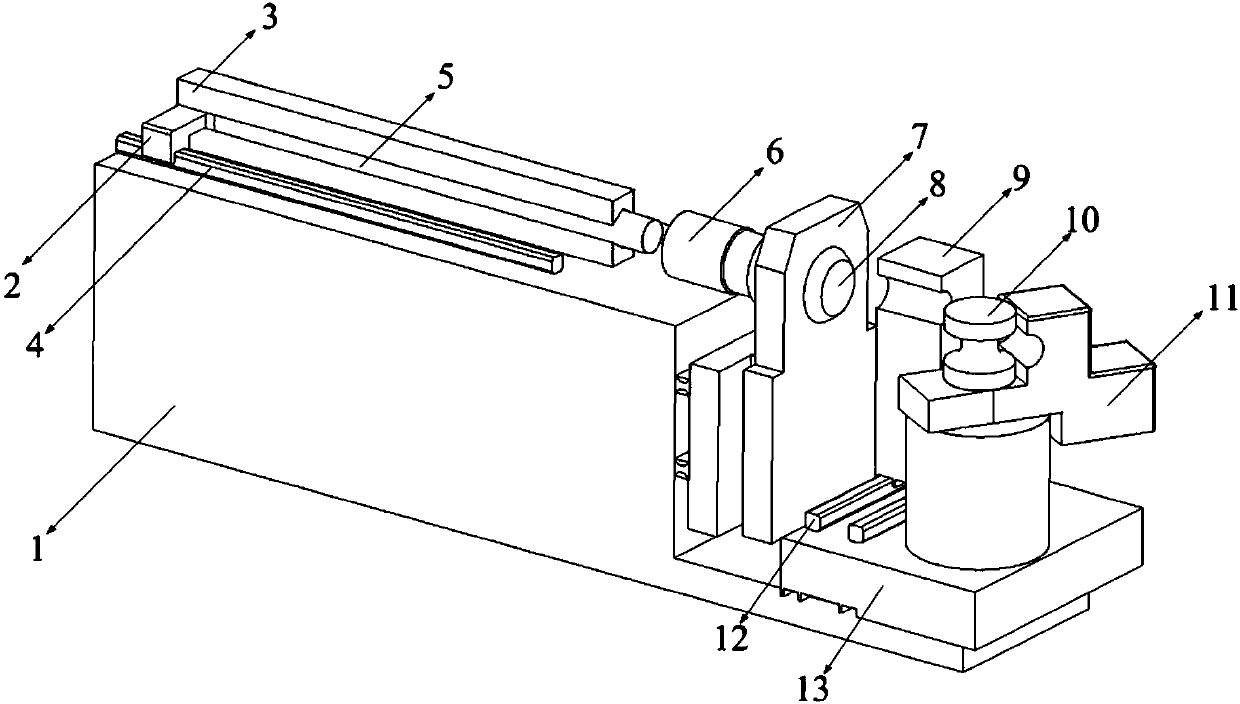
[0027] like figure 1 As shown, the three-dimensional free bending and numerically controlled bending composite forming equipment of the present invention includes a frame 1, a feeding mechanism, a free bending forming mechanism, and a numerically controlled bending forming mechanism. The free bending forming mechanism and the numerically controlled bending forming mechanism share a feeding mechanism, and the numerically controlled bending The forming mechanism is placed at the front end of the free bending forming mechanism; the specific structure of each part is as follows:

[0028] 1. Feeding mechanism:

[0029] Including the pipe clamping device 3, the propulsion device 2 and the linear guide rail I4; the pipe clamping device is used to clamp the tube blank 5 to be formed to prevent the axial instability of the pipe during the forming process; the linear guide ra...


PUM


Abstract

The invention discloses three-dimensional free bending and numerical-control winding combined molding equipment and belongs to the field of metal complex hollow component molding equipment. The equipment comprises a rack, a feeding mechanism, a free bending molding mechanism and a numerical-control winding molding mechanism. The feeding mechanism comprises a pipe material clamping device, a propelling mechanism and a linear guide rail I, wherein the pipe material clamping device is used for preventing a pipe material from losing stability in the axial direction in the molding process. The freebending molding mechanism comprises a guiding mechanism, a spherical bearing and a free bending mold. The free bending mold rotates around the guiding mechanism under the effect of the spherical bearing, so that free bending molding of the pipe material is achieved. The numerical-control winding molding mechanism comprises a clamping block and a numerical-control winding bending mold. The clamping block rotates around the numerical-control winding bending mold, so that molding is achieved. By means of the three-dimensional free bending and numerical-control winding combined molding equipment,free bending molding of a complex bending component can be achieved, and meanwhile, molding of a blank with the minimum bending radius being as low as 1.5D can be achieved, wherein D represents the outer diameter of the blank.

Description

technical field [0001] The invention relates to the technical field of forming and manufacturing metal complex bending components, in particular to a three-dimensional free bending and numerically controlled bending composite forming equipment. Background technique [0002] Metal complex bending components have broad application value in aerospace, nuclear power, automobile, ship and other fields because of their advantages such as complex spatial structure and integral forming. The three-dimensional free bending forming technology can realize the precise moldless forming of complex bending components such as spiral and S-shaped bends. Different bending radii can be achieved only by controlling different eccentricities of the bending dies. At the same time, the three-dimensional free bending forming technology can completely eliminate the straight sections between different curved sections. However, the existing three-axis, five-axis and six-axis free bending forming equip...

Claims


Application Information

Patent Timeline
IPC IPC(8): B21D11/06
CPCB21D11/06
Inventor 徐勇郭训忠张士宏陶杰马燕楠
Owner INST OF METAL RESEARCH - CHINESE ACAD OF SCI
Learn More