Shaft sleeve turning tool

A shaft sleeve and turning technology, applied in the field of machining, can solve problems such as the increase of product defect rate, and achieve the effect of improving accuracy, position accuracy and efficiency

Pending Publication Date: 2018-04-20
重庆市璧山区四通机械厂
View PDF10 Cites 1 Cited by
  • Summary
  • Abstract
  • Description
  • Claims
  • Application Information

AI Technical Summary

Problems solved by technology

The existing turning tooling usually sets a limit part on the clamping part of the shaft sleeve to fix the position of the shaft sleeve in the axial direction, and then adjusts the position of the tool according to the position of the end face of the shaft sleeve to be turned, so that it can adjust the position of the shaft sleeve Turning is performed on the end face of the above-mentioned turning tool. When adjusting the position of the tool, the position of the tool is adjusted manually, so errors are inevitable, resulting in an increase in the defective rate of the product.

Method used


Image

  • Shaft sleeve turning tool

Examples


Embodiment Construction

[0012] In order to enable those skilled in the art to better understand the present invention, the technical solution of the present invention will be further described below in conjunction with the accompanying drawings and embodiments.

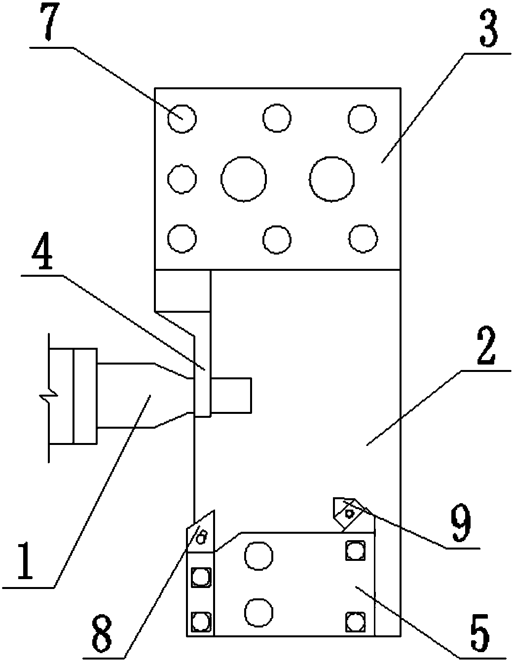
[0013] Such as figure 1 As shown, a bushing turning tool includes a three-jaw chuck, a bushing clamping member 1 arranged on the three-jaw chuck, a tool rest 2 that can move horizontally or vertically on a lathe, and the tool The frame 2 is provided with a limiting mechanism and a turning mechanism, and the limiting mechanism includes a base 3 and a limiting member 4 for limiting the installation position of the bushing, and the limiting member 4 is arranged on the base 3; The turning mechanism includes a tool holder 5 and a tool for turning the bushing, the cutter is arranged on the cutter holder 5, the base 3 and the cutter holder 5 are arranged on the tool holder 2 and are respectively located on both sides of the bush clamping part 1; T...


PUM


Abstract

The invention discloses a shaft sleeve turning tool which comprises a three-jaw chuck, a shaft sleeve clamping part and a cutter rest. The shaft sleeve clamping part and the cutter rest are arranged on the three-jaw chuck. The cutter rest is provided with a limiting mechanism and a turning mechanism. The limiting mechanism comprises a base and a limiting part used for limiting the installation position of a shaft sleeve. The limiting part is arranged on the base. The turning mechanism comprises a cutter base and a cutter for turning the shaft sleeve. The cutter is arranged on the cutter base.The base and the cutter base are arranged on the cutter rest and located on the two sides of the shaft sleeve clamping part correspondingly. The plane where the portion, making contact with the end face of the shaft sleeve, of the cutter is located and the plane where the portion, making contact with the end face of the shaft sleeve, of the limiting part are located in the same plane. By means ofthe shaft sleeve turning tool, turning precision is improved, the shaft sleeve fixing position is more accurate, the efficiency is improved compared with an existing shaft sleeve turning tool, and meanwhile the problem that an existing turning tool only can machine the end face of the end, away from the limiting pat, of the shaft sleeve, and the other end face only can be manually machined is solved.

Description

technical field [0001] The invention relates to the technical field of mechanical processing, in particular to a tool for turning a shaft sleeve. Background technique [0002] The three-jaw chuck is composed of a chuck body, movable jaws and jaw driving mechanism. It is a machine tool accessory for clamping and positioning the workpiece by using the radial movement of the three movable jaws evenly distributed on the chuck body. [0003] When turning the end face of the bushing, the three movable jaws of the three-jaw chuck are usually extended along the axial direction with supporting blocks to form a cylindrical bushing clamping part for fixing the bushing. The clamping part clamps and fixes the shaft sleeve, and then the end face of the shaft sleeve is turned by a tool. The existing turning tooling usually sets a limit part on the clamping part of the shaft sleeve to fix the position of the shaft sleeve in the axial direction, and then adjusts the position of the tool acc...

Claims


Application Information

Patent Timeline
Patent Type & Authority Applications(China)
IPC IPC(8): B23Q3/12B23B31/103B23B3/06
CPCB23B3/06B23B31/103B23Q3/12B23Q2703/10
Inventor 孙良帮杨建平孙绍洋欧文辉
Owner 重庆市璧山区四通机械厂
Why Eureka
Try Eureka