Eureka AIR delivers breakthrough ideas for toughest innovation challenges, trusted by R&D personnel around the world.

Twisting force control method and device of polishing wheel and polisher system

A control device and polishing wheel technology, applied in the field of polishing machines, can solve the problems of polishing wheel wear, product quality cannot be guaranteed, and workpiece surface polishing cannot be achieved, so as to achieve the effect of improving quality

Active Publication Date: 2018-04-20
SHENZHEN CITY POSONWONE TECH
View PDF7 Cites 4 Cited by
  • Summary
  • Abstract
  • Description
  • Claims
  • Application Information

AI Technical Summary

Problems solved by technology

After the polishing machine has been working for a period of time, the polishing wheel will be worn out, and there will be a distance between the polishing wheel and the product surface, which may not be able to polish the workpiece surface, resulting in the failure to guarantee product quality
In the prior art, in order to solve this problem, the distance and pressure between the polishing wheel and the surface of the workpiece are generally adjusted manually. The defect is that on the one hand, the adjustment is made after defective products have appeared, so it is difficult to avoid defective products in the product. On the other hand, the efficiency of manual adjustment is low

Method used


Image

  • Twisting force control method and device of polishing wheel and polisher system
  • Twisting force control method and device of polishing wheel and polisher system
  • Twisting force control method and device of polishing wheel and polisher system

Examples


Embodiment Construction

[0034] It should be understood that the specific embodiments described here are only used to explain the present invention, not to limit the present invention.

[0035] Embodiments of the present invention are described in detail below, examples of which are shown in the drawings, wherein the same or similar reference numerals designate the same or similar elements or elements having the same or similar functions throughout. The embodiments described below by referring to the accompanying drawings are exemplary and are intended to explain the present invention, but cannot be construed as limitations to the present invention. Based on the embodiments in the present invention, those skilled in the art do not make creative work premise All other embodiments obtained below all belong to the protection scope of the present invention.

[0036] In the description of the present invention, it should be understood that the terms "first" and "second" are used for description purposes on...


PUM


Abstract

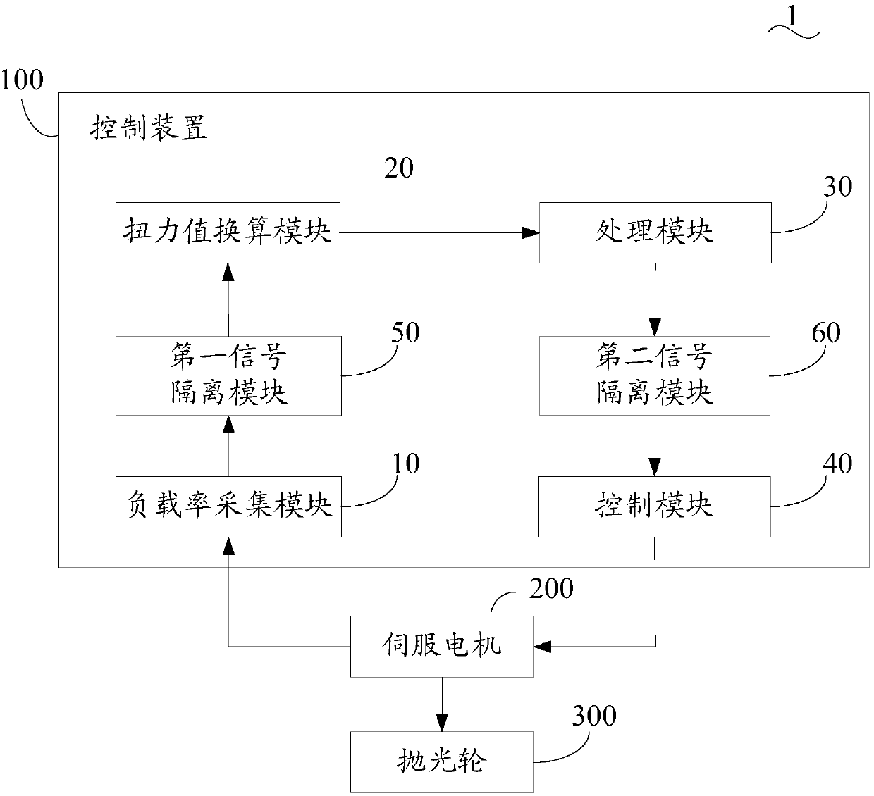
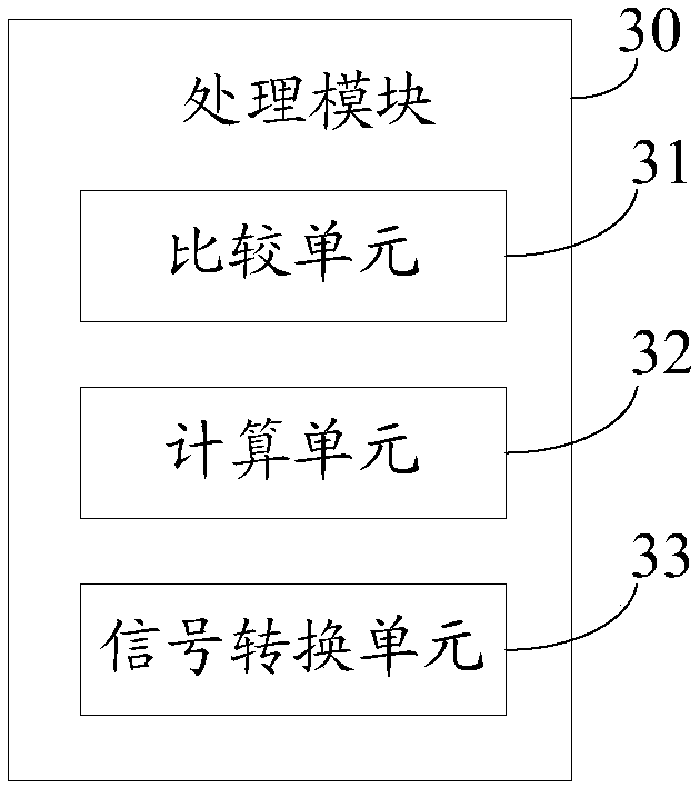
The invention discloses a polisher system. The polisher system comprises a polishing wheel, a servo motor driving the polishing wheel to rotate and a control device driving the servo motor to operate.The control device comprises a load rate collection module, a twisting force value conversion module, a processing module and a control module. The load rate collection module is used for collectingthe load rate of the servo motor in real time when the polishing wheel is driven by the servo motor to operate. The twisting force value conversion module is used for carrying out conversion processing on the load rate of the servo motor and acquiring the twisting force value of the polishing wheel. The processing module is used for generating adjusting parameters of the servo motor according to the twisting force value of the polishing wheel. The control module is used for controlling operation of the servo motor according to the adjusting parameters so that the twisting force value of the polishing wheel can be within the preset twisting force value range. The polisher system is disclosed and comprises the control device. Automatic control over a polisher is achieved, and the quality ofworkpieces machined by the polisher is improved.

Description

technical field [0001] The invention relates to the field of polishing machines, in particular to a method and device for controlling the torque of a polishing wheel, and a polishing machine system. Background technique [0002] The polishing machine mainly uses the motor to drive the polishing wheel to rotate at high speed to produce rolling and cutting on the surface of the workpiece, so as to obtain a bright processed surface. During the process of workpiece processing by the polishing machine, maintaining the friction between the polishing wheel and the workpiece and the speed of the polishing wheel are stable, which are the key indicators of the processing quality of the workpiece. After the polishing machine has been working for a period of time, the polishing wheel will be worn out, and there will be a distance between the polishing wheel and the surface of the product. It may not be possible to polish the surface of the workpiece, resulting in that the product qualit...

Claims


Application Information

Patent Timeline
Patent Type & Authority Applications(China)
IPC IPC(8): B24B29/00B24B51/00G05D17/02
CPCB24B29/00B24B51/00G05D17/02
Inventor 王立军
Owner SHENZHEN CITY POSONWONE TECH
Why Eureka
Eureka Blog
Learn More